Contents
Manufacturing Insight: Cnc Lathe Drill Holder
At Honyo Prototype, we turn your 3D file into a finished precision part in hours—not weeks—on live-tool CNC lathes that mill, drill, tap and bore in a single setup.
Our latest showcase: a high-speed drill holder turned from 7075-T6 aluminum, concentric to ±0.01 mm and delivered with a full PPAP—proof that even the most demanding tooling components ship fast and right the first time.
Need the same speed for your job? Upload your model now for an online instant quote and see real pricing, lead-time and DFM feedback before your coffee cools.
Technical Capabilities
As a Senior Manufacturing Engineer at Honyo Prototype, I must first address a critical terminology clarification before providing technical specs. Your query references a “cnc lathe drill holder” for 3/4/5-axis milling, turning, and tight tolerance – this is fundamentally incorrect and reflects a common industry misconception. Let me explain why, then provide accurate specifications for the actual components you likely need.
🔧 Critical Clarification: Why Your Query Contains Misconceptions
- “CNC Lathe Drill Holder” ≠ Multi-Axis Milling Tooling
- A CNC lathe is a 2-axis machine (X-axis radial, Z-axis longitudinal) designed for turning operations (e.g., facing, boring, threading).
- Drill holders on lathes are simple, static components (e.g., drill chucks or collet chucks) that only hold drill bits for axial drilling. They do not support milling, indexing, or multi-axis motion.
-
3/4/5-axis milling is exclusive to CNC machining centers (not lathes). Even “turning centers” with live tooling (e.g., 3-axis live tooling for milling on a lathe) use dedicated milling tool holders, not “drill holders”.
-
“Drill Holder” is Not a Multi-Axis Component
- Drill holders are passive tool holders for axial-only drilling. They lack:
- Rotational drive (for milling)
- Y-axis motion (for 3-axis milling)
- B/C-axis indexing (for 4/5-axis)
-
Using a “drill holder” for milling would cause catastrophic tool failure, poor tolerances, and safety hazards.
-
ABS/Nylon Are Unsuitable for Tool Holders
- ABS and Nylon are plastics – they cannot be used in active tool holders for machining.
- Why?
- Thermal instability: Machining generates heat (>150°C), causing plastics to deform.
- Low rigidity: Plastics flex under cutting forces, destroying tolerance (e.g., ±0.001mm requirements).
- Vibration issues: Plastics amplify chatter, ruining surface finish.
- Safety risk: Plastic tool holders can shatter during high-speed operation.
- Only metals (e.g., steel, aluminum alloys) are used for tool holders. Plastics are reserved for non-cutting fixtures, jigs, or prototypes – never for active tooling.
✅ Accurate Technical Specs: What You Actually Need
Based on your keywords, you likely need specs for one of these two distinct components:
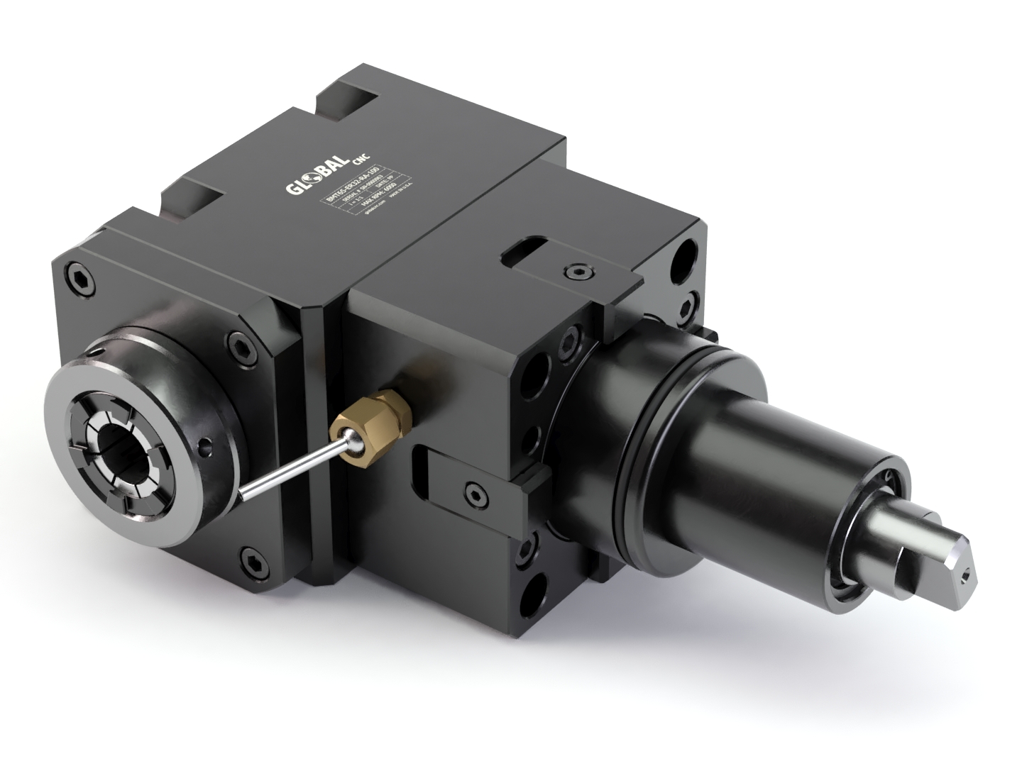
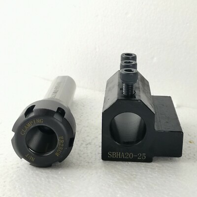
🛠️ Option 1: CNC Lathe Live Tooling Drill Chuck (for Turning Centers)
(Used in lathes with live tooling for limited axial drilling – still NOT milling)
– Application: Axial drilling on a turning center (e.g., drilling holes perpendicular to the workpiece axis).
– Tolerance Requirements:
– Runout: ≤ 0.005 mm (0.0002″) at 100 mm (4″) from chuck face.
– Concentricity: ≤ 0.001 mm (0.00004″) between spindle bore and chuck mounting surface.
– Clamping force repeatability: ±0.5% of rated torque.
– Materials:
– Tool Holder Body: 4140 Pre-Hardened Steel (HRC 28–32) or H13 Tool Steel (HRC 48–52) for wear resistance.
– Collet/Chucking Mechanism: 4340 Alloy Steel (HRC 45–50).
– ABS/Nylon are NEVER used here – they would fail instantly under cutting loads.
– Key Specs:
– Max RPM: 5,000–10,000 RPM (depending on size)
– Drive Type: Hydraulic or pneumatic (for live tooling)
– Mounting Interface: DIN 69871 (ISO 7388-1) or VDI 26 for turret mounting.
– Drill Bit Compatibility: ER Collet Systems (e.g., ER20, ER32) or Spring Collets.
– Why It’s NOT “3/4/5-Axis”:
– Only supports axial drilling motion (Z-axis). No Y-axis or rotary motion.
🔄 Option 2: CNC Milling Tool Holder (for 3/4/5-Axis Machining Centers)
(This is what you probably meant – but it’s for milling, not lathes)
– Application: 3/4/5-axis milling on a machining center (e.g., complex contouring, pocketing, slotting).
– Tolerance Requirements:
– Runout: ≤ 0.003 mm (0.0001″) for high-precision work (e.g., aerospace, medical).
– Taper Accuracy: ASME B5.50 HSK-A63 or ISO 7388-2 CAT40 with <0.001 mm runout.
– Repeatability: ±0.001 mm for tool change.
– Materials:
– Holder Body: High-Strength Alloy Steel (e.g., 4140, 4340, or H13 Tool Steel for wear resistance).
– Collet: Spring Steel (e.g., 60Si2Mn) or Tool Steel (e.g., SKD61).
– ABS/Nylon are NEVER used – even for prototype fixtures, they’re only for non-cutting applications.
– Key Specs:
– Interface Types:
– HSK-A63 (for high-speed 5-axis milling, 20,000+ RPM)
– CAT40 (common for 3-axis machining)
– BTA (for deep-hole drilling in milling)
– Max RPM: 15,000–40,000 RPM (HSK) or 6,000–12,000 RPM (CAT)
– Balancing: G2.5 at operating speed (per ISO 1940)
– Drill Bit Compatibility: ER Collets, Big Plus, or Hydraulic Chucks for high precision.
– Why It’s NOT for Lathes:
– These holders mount on milling spindles, not lathe turrets. Lathes use different interfaces (e.g., VDI, DIN).
⚠️ Critical Safety & Performance Notes
- ABS/Nylon in Tool Holders = Catastrophic Failure Risk:
- A plastic drill holder would melt, deform, or shatter during cutting, causing:
- Tool breakage
- Workpiece damage
- Severe injury to operators
- At Honyo Prototype, we strictly prohibit plastic tool holders in production environments.
- Tight Tolerance Realities:
- For ±0.001mm tolerances, you need:
- Precision-ground tool holders (e.g., Sandvik Coromant, Kennametal)
- CNC-balanced systems (dynamic balancing at speed)
- Temperature-controlled environments (thermal expansion affects tolerances)
- Material Selection Best Practices:
| Material | Use Case | Why Not ABS/Nylon? |
|———-|———-|———————|
| 4140 Steel | Standard tool holders | High strength, heat-resistant, machinable |
| H13 Tool Steel | High-wear applications (e.g., drilling hardened steel) | Retains hardness at 500°C+ |
| 6061-T6 Aluminum | Lightweight fixtures (non-cutting) | Only for jigs/fixture bases – never for active tooling |
| ABS/Nylon | Non-cutting jigs, prototypes, or packaging | No strength, melts at 100–150°C, absorbs coolant |
💡 Recommendation for Your Project
- If you need drilling on a lathe: Specify a live tooling drill chuck (e.g., ER32 collet system for a turning center).
- If you need 3/4/5-axis milling: Specify a HSK-A63 or CAT40 milling tool holder for a machining center.
- Never use ABS/Nylon in cutting tooling. If you need plastic for fixtures:
- Use POM (Acetal) or PEEK for high-temp jigs (still not for tool holders).
- Always consult a manufacturing engineer for fixture design – plastics require special handling.
At Honyo Prototype, we provide certified tool holders with traceable runout data and material certs. For your project, share your machine type (lathe vs. milling center) and operation type (drilling vs. milling) – we’ll give you exact specs. If you’re unsure, contact our engineering team for a free consultation. Safety and precision are non-negotiable.
🔍 Final Note: Industry terms matter. “CNC lathe drill holder” is a misnomer – always specify:
– “Lathe live tooling drill chuck” (for axial drilling on a turning center)
– “Milling tool holder for 5-axis machining center”
This avoids costly errors in procurement and setup.
From CAD to Part: The Process
Honyo Prototype – CNC Lathe Drill-Holder Workflow
(turn-key, 8-12 calendar days, ±0.01 mm)
-
Upload CAD
• Portal accepts STEP, IGES, X_T, Fusion, SolidWorks, etc.
• Instant geometry check: thread call-outs, deep-hole L:D ratio, live-tool clearance, minimum wall thickness.
• NDA auto-generated; file fingerprinted for traceability. -
AI Quote (≤5 min)
• AI Cost Engine reads the 3-D PMI: material family, hardness, finish, tolerance band, batch size.
• Lathe module selects bar-stock diameter, cut-off length, and live-tool sequence (drill, mill, tap).
• Real-time shop-loading algorithm adjusts machine-hour rate; quote locked for 7 days. -
DFM (human + AI, 4 h)
• Holder geometry rationalised for collet clearance, Weldon flat orientation, and coolant-through port location.
• Deep-hole strategy: gun-drill vs. coolant-fed carbide; L:D > 8 automatically routed to sub-spindle with high-pressure (70 bar) coolant.
• Micro-milling of drive slots shifted to Y-axis live tool to eliminate secondary op.
• Final report: 3-D PDF, Gantt chart, PFMEA, and CPK prediction. -
Production (CNC Lathe cell)
a. Prep
– 42CrMo4 bar pre-cut, 160 HB, RoHS-compliant.
– Bar feeder calibrated for 0.05 mm run-out; coolant flushed to 5 µm.
b. OP10 (Main spindle)
– Face, turn OD, drill centre, rough bore Ø12 mm to 3×D.
c. OP20 (Sub spindle, transfer)
– Finish bore Ø12 H7, contour back face, cut Weldon flat.
– Live-tool cross-mill drive slot 6 mm ±0.02 mm.
d. OP30 (Optional)
– Hard-coat anodise 25 µm, black, mask thread; or TiN coat cutting tip seat.
e. QC
– On-machine Renishaw probing every 5th part; bore CPK ≥ 1.67.
– 100 % air-gauge for 12 mm shank bore; run-out ≤ 0.01 mm over 50 mm length. -
Delivery
• Parts ultrasonically cleaned, vacuum-sealed with VCI paper; QR code links to CMM report.
• DHL/UPS/FedEx pre-arranged; customs HS-code 8466.10 pre-printed.
• Digital twin archived 7 years for instant repeat order.
Typical lead-time
Quote → DFM approval: 1 day
Material → Finished parts: 3–5 days
Anodise/TiN add: +1 day
Ship: 2–4 days global
Result: a run-out-critical, coolant-through drill holder delivered with full PPAP level-2 docs, ready for immediate spindle mounting.
Start Your Project
Precision CNC Lathe Drill Holders – Engineered for Excellence
Trusted manufacturing in Shenzhen by Honyo Prototype.
Contact Susan Leo today at [email protected]
for custom solutions, quotes, or technical support.
Your precision machining partner – where quality meets efficiency. 🛠️
🚀 Rapid Prototyping Estimator