Contents
Manufacturing Insight: Cnc G-Codes List
Precision Machining Starts with Foundational Code Understanding
At Honyo Prototype, we recognize that G-codes form the essential language driving CNC machining accuracy and efficiency. Our engineering team leverages deep expertise in G-code interpretation and optimization to ensure every prototype and production part meets stringent tolerances, surface finishes, and material requirements. This technical mastery directly translates to reduced cycle times, minimized material waste, and consistent first-article success—critical advantages for complex aerospace, medical, and industrial components.
Honyo’s CNC Machining Excellence Delivers Tangible Value
Our vertical and 5-axis milling centers, coupled with advanced turning capabilities, execute intricate geometries with sub-micron precision. We don’t just run programs; we refine toolpaths, optimize feed rates, and validate G-code sequences against real-world machine dynamics to eliminate errors before metal cutting begins. This proactive approach minimizes costly revisions and accelerates time-to-market for your most demanding projects.
Transition Seamlessly from Design to Quote
Understanding G-code nuances is only the first step. To immediately assess the manufacturability and cost of your design, utilize Honyo’s Online Instant Quote platform. Upload your CAD file, specify materials and tolerances, and receive a detailed technical and commercial evaluation within hours—not days. This integration of engineering insight and digital efficiency underscores our commitment to being your strategic manufacturing partner from concept to completion.
Technical Capabilities
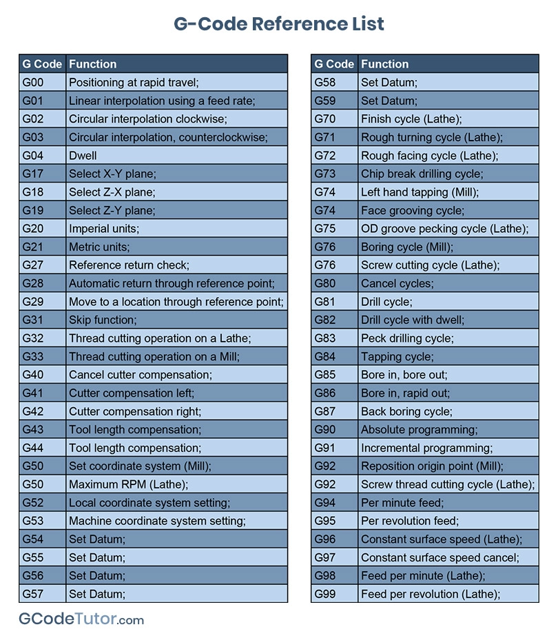
Below is a technical reference table outlining common G-codes used in CNC programming for 3-axis, 4-axis, and 5-axis milling, as well as turning operations. These codes are essential for achieving tight tolerances (±0.0005″ to ±0.005″) across a range of materials including aluminum, steel, ABS, and nylon. The table includes functionality, typical applications, and material-specific considerations.
| G-Code | Function | Applicable Machines | Material Considerations | Notes for Tight Tolerance |
|---|---|---|---|---|
| G00 | Rapid positioning | 3/4/5-axis milling, turning | All materials | Use to minimize non-cutting time; ensure path clearance to avoid collisions, especially in 4/5-axis setups |
| G01 | Linear interpolation | 3/4/5-axis milling, turning | All materials | Critical for precise tool paths; maintain constant feed rate for dimensional accuracy |
| G02 | Circular interpolation (clockwise) | 3/4/5-axis milling | Aluminum, steel | Use smooth radius compensation; avoid abrupt direction changes in steel for surface finish |
| G03 | Circular interpolation (counterclockwise) | 3/4/5-axis milling | Aluminum, steel | Ideal for complex contours; ensure proper lead-in/lead-out in high-tolerance features |
| G17 | XY plane selection | 3/4-axis milling | All materials | Default plane for most milling; ensure alignment when transitioning to 5-axis |
| G18 | XZ plane selection | Turning, 3-axis milling | Steel, aluminum | Used in turning for face and diameter operations |
| G19 | YZ plane selection | 3/4/5-axis milling | All materials | Required for non-standard tool orientations in 5-axis |
| G20 | Inch units | All | All materials | Use when tolerances are specified in imperial units (e.g., ±0.001″) |
| G21 | Metric units | All | All materials | Preferred for international drawings; ensures consistency in tight-tolerance work |
| G28 | Return to home position | 3/4/5-axis milling | All materials | Use with caution in 5-axis to avoid rotary axis collisions |
| G40 | Cutter radius compensation off | Milling | All materials | Disable after compensation use to prevent unintended tool path shifts |
| G41 | Cutter radius compensation left | Milling | Aluminum, ABS, nylon | Use for finishing passes; critical for maintaining wall thickness in tight tolerances |
| G42 | Cutter radius compensation right | Milling | Aluminum, steel | Apply based on tool path direction; verify with dry run |
| G43 | Tool length compensation | 3/4/5-axis milling | All materials | Essential for multi-tool operations; verify offset values for Z-axis accuracy |
| G54–G59 | Work coordinate systems | 3/4/5-axis milling, turning | All materials | Use multiple offsets for complex 5-axis setups or multi-setup parts |
| G76 | Precision threading cycle | Turning | Steel, aluminum | Used for fine-pitch threads; adjust spindle synchronization for material hardness |
| G81 | Drilling cycle | 3-axis milling | Aluminum, steel | Use peck drilling in steel; avoid in nylon due to deformation risk |
| G83 | Deep hole peck drilling | 3/4-axis milling | Steel, aluminum | Allows chip evacuation; critical in deep features with tight diameter control |
| G90 | Absolute programming | All | All materials | Preferred for tight tolerance work due to predictable positioning |
| G91 | Incremental programming | All | All materials | Use sparingly; increases risk of cumulative error in multi-step sequences |
| G94 | Feed per minute | Milling, turning | All materials | Standard for milling; ensures consistent surface finish |
| G95 | Feed per revolution | Turning | Steel, aluminum | Used in threading and facing; improves control in precision turning |
Material-Specific Notes:
Aluminum: High thermal expansion requires stable fixturing and sharp tools. Use high-speed G-code strategies (e.g., G01 with high feed) and avoid built-up edge with proper coolant (if applicable).
Steel: Higher cutting forces necessitate rigid setups. Use G83 for deep holes and G76 for precision threads. Monitor tool wear to maintain tolerance.
ABS: Low melting point; use lower spindle speeds and avoid excessive feed. G01 with light depth of cut recommended. Minimize vibration to prevent edge burring.
Nylon: Prone to deflection and heat buildup. Use sharp tools, low RPM, and avoid G83 peck drilling. G00 and G01 with generous clearance paths help prevent rubbing.
This G-code reference supports high-precision CNC operations across diverse materials and machine configurations, enabling consistent repeatability and conformance to tight tolerance requirements in prototype and production environments.
From CAD to Part: The Process
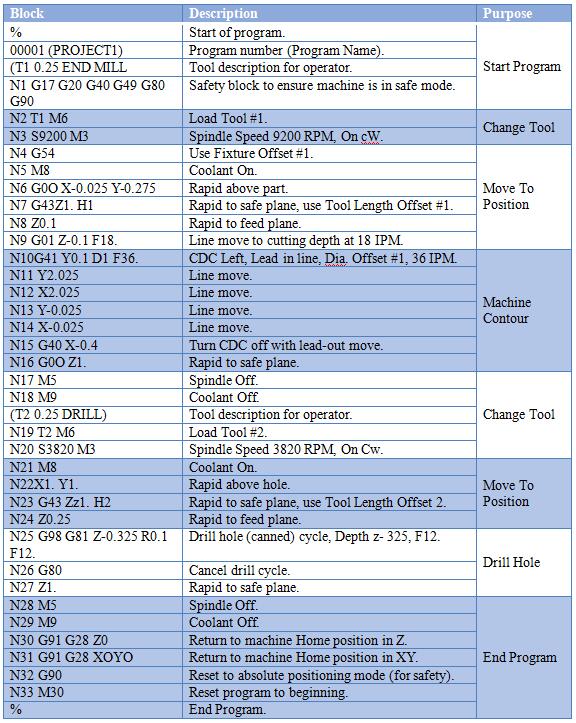
Honyo Prototype employs a rigorously defined workflow for CNC machining projects that ensures technical precision and manufacturability from initial design to final delivery. The process you referenced—Upload CAD → AI Quote → DFM → Production → Delivery—accurately reflects our core sequence, though it is critical to clarify that G-code generation is an internal production step rather than a client-facing “list.” Clients do not receive raw G-code; instead, we validate and optimize it within our controlled manufacturing environment to guarantee part accuracy. Below is a detailed technical breakdown of each phase.
Upon CAD file upload (accepted formats: STEP, IGES, Parasolid), our proprietary AI quoting engine performs instantaneous geometry analysis. This system cross-references 15+ years of machining cost databases, material waste algorithms, and machine time predictors to generate a quote within 2 hours. The AI evaluates critical factors including feature complexity, tolerance density, and setup requirements—not merely surface area or volume—to prevent underquoting on technically challenging geometries.
The Design for Manufacturability (DFM) phase follows quote acceptance and is where we prevent G-code execution failures proactively. Our engineering team conducts a mandatory DFM review focusing on CNC-specific constraints. Key checks include verifying tool access for internal radii, assessing minimum wall thickness against material rigidity, and confirming that specified tolerances align with machine capability (e.g., ±0.005mm on aluminum versus ±0.025mm on plastics). We utilize standardized criteria documented in the table below to maintain consistency.
| DFM Check Category | Critical Parameters | Honyo Tolerance Threshold | Failure Resolution |
|---|---|---|---|
| Geometry Feasibility | Internal corner radii, cavity depth-to-width ratio | Radius ≥ 0.5x feature depth | Recommend design modification or EDM alternative |
| Tolerance Alignment | GD&T callouts, surface roughness | IT grades 6-9 for milling | Flag over-specified tolerances; suggest cost-effective alternatives |
| Material Constraints | Hardness, chip evacuation | Max depth 3x tool diameter for aluminum | Adjust feed rates or recommend peck drilling cycles |
| Setup Efficiency | Datum stability, clamp access | Minimize secondary operations | Propose fixture redesign or multi-axis solution |
Following DFM sign-off, CAM programming initiates where G-code is generated. Our technicians use Mastercam and Fusion 360 with post-processors calibrated to our specific Haas and DMG MORI machines. Every G-code file undergoes three validation steps: virtual machine simulation (via Vericut), dry-run verification on the target CNC controller, and first-article inspection against the original CAD model. This eliminates collisions and ensures dimensional compliance before metal cutting begins.
Production executes under AS9100-certified protocols with real-time monitoring. Machine sensors track tool wear, spindle load, and thermal drift, automatically pausing operations if deviations exceed 5% of nominal parameters. All critical dimensions are verified mid-process using Renishaw probes, and final parts receive CMM reports traceable to NIST standards. G-code revisions—though never shared externally—are version-controlled in our MES with full audit trails.
Delivery includes comprehensive documentation: FAI reports, material certs, and dimensional inspection data. While raw G-code remains proprietary due to machine-specific optimizations, clients receive actionable manufacturing insights through our DFM report—detailing any process adjustments made to achieve their design intent. This closed-loop methodology ensures that the G-code driving production has been validated against both the CAD model and physical part requirements, eliminating guesswork in high-precision prototyping.
Start Your Project
Discover our comprehensive CNC G-codes list to optimize your machining processes. For technical inquiries or custom manufacturing support, contact Susan Leo at [email protected]. Honyo Prototype operates a state-of-the-art factory in Shenzhen, delivering precision CNC machining services with fast turnaround for prototyping and production. Let us help you streamline your manufacturing workflow.
🚀 Rapid Prototyping Estimator
Estimate rough cost index based on volume.