Contents
Manufacturing Insight: Cnc G-Code
Understanding CNC G-Code: The Precision Language Powering Your Prototypes
CNC G-Code is the fundamental programming language that precisely directs every movement and operation of computer numerical control (CNC) machining centers. It translates complex CAD/CAM designs into meticulously coordinated instructions for spindle speed, tool path, feed rate, and coolant control, enabling the creation of parts with exceptional accuracy and repeatability. At Honyo Prototype, we recognize that mastery of G-Code generation and optimization is not merely a technical step but the critical foundation for achieving true manufacturing excellence in rapid prototyping and low-volume production.
Our dedicated team of expert CNC programmers and manufacturing engineers possesses deep, practical knowledge of G-Code intricacies across milling, turning, and multi-axis platforms. We go beyond basic code generation, employing advanced simulation and strategic optimization techniques to ensure every line of G-Code maximizes machine efficiency, minimizes cycle times, and consistently delivers parts meeting stringent sub-micron tolerance requirements. This technical proficiency, combined with our state-of-the-art HAAS and DMG MORI equipment, allows Honyo Prototype to tackle the most demanding geometries and challenging materials with confidence, turning your complex designs into high-fidelity physical prototypes faster and more reliably.
Leveraging our precision CNC machining capabilities, including 3-axis, 4-axis, and 5-axis milling alongside precision turning, ensures your prototypes function exactly as intended, accelerating your design validation and time-to-market. To streamline your path from concept to physical part, Honyo Prototype offers an Online Instant Quote system. Simply upload your 3D CAD model (STEP, IGES, Parasolid, or native formats), specify your material and quantity requirements, and receive a detailed, transparent manufacturing quote within seconds – no waiting, no follow-up calls required. Experience the efficiency and precision of Honyo Prototype’s CNC machining services, powered by expert G-Code execution and designed for the speed your development cycle demands.
Technical Capabilities
CNC G-Code Technical Specifications for 3/4/5-Axis Milling, Turning, and Tight Tolerance Applications
G-code (Geometric Code) is the standard programming language used to control CNC (Computer Numerical Control) machine tools. It provides precise instructions for tool paths, speeds, feeds, spindle control, and coordinate positioning. The following table outlines key technical considerations and specifications for G-code in high-precision 3-axis, 4-axis, and 5-axis milling, as well as turning operations, with emphasis on tight-tolerance work and common engineering materials.
| Parameter | 3-Axis Milling | 4-Axis Milling | 5-Axis Milling | CNC Turning | Notes on Tight Tolerance (±0.0005″ / ±0.013 mm) |
|---|---|---|---|---|---|
| Coordinate Axes Controlled | X, Y, Z | X, Y, Z, A (rotary around X) | X, Y, Z, A, B (or C) | X, Z (primary), C (optional for live tooling) | 5-axis enables complex undercuts and single-setup precision |
| Typical G-Codes Used | G00 (rapid), G01 (linear), G02/G03 (arc), G17/G18/G19 (plane selection), G43 (tool length comp) | All 3-axis codes + G10 (tool offset), G54.4 (work offset for 4th axis) | Full 3-axis + rotary interpolation (G04, G6.2, G6.3), G43.4 (tool vector comp) | G00, G01, G71–G76 (cycle rough/finish), G90/G94 (turning cycles) | Use of G05.1 Q1 (look-ahead) and G64 (continuous path) for smooth motion and accuracy |
| Tolerance Capability | ±0.001″ (±0.025 mm) standard; ±0.0005″ achievable with tooling and setup | ±0.0008″ typical; ±0.0005″ with precision rotary | ±0.0005″ to ±0.0002″ with high-end machines and calibration | ±0.0005″ on diameter and length with fine finish cycles | Requires thermal stability, rigid fixturing, and in-process probing (G31, G27) |
| Spindle Speed Range (RPM) | 8,000–20,000 (milling) | 8,000–15,000 | 10,000–24,000 (high-speed machining) | 500–6,000 (steel), up to 12,000 (aluminum) | High RPM with balanced tooling improves surface finish and accuracy |
| Feed Rates (IPM) | 50–800 (depending on material and tool) | 40–600 | 60–1,200 (HSM paths) | 0.002–0.015 ipr (inches per revolution) | Adaptive feeds (G94/G95) and constant surface speed (G96) optimize finish |
| Common Materials Processed | Aluminum (6061, 7075), Steel (1018, 4140), ABS, Nylon | Same as 3-axis, with improved access for complex parts | Aerospace alloys (Ti-6Al-4V), hardened steels, composites | Aluminum, Steel, Stainless, ABS (for prototypes), Nylon (engineering grades) | Material affects tool selection, coolant use, and deflection control |
| Tooling Compensation | G41/G42 (cutter radius), G43 (length) | Same, plus A-axis tilt compensation | Full tool vector compensation (G43.4, G43.5) | G41/G42 for insert nose radius | Critical for tight tolerance; must be verified with touch probes |
| Coolant & Lubrication Control | M08 (flood), M07 (mist), M41/M42 (high/low range) | Same; through-spindle coolant (M52/M53) recommended | High-pressure coolant (M08.2) for chip evacuation | M08/M09, often with through-tool coolant | Essential for thermal stability and surface integrity |
| Workholding & Fixturing | Vises, clamps, tombstones | Rotational fixtures, indexer bases | 5-axis trunnions, custom fixtures | Chucks, collets, steady rests | Fixtures must minimize runout (<0.0002″) and vibration |
| Surface Finish (Ra, µin) | 32–125 (standard), 16–32 (precision) | 32–64, down to 8 with polishing passes | 16–32 (typical), 4–8 with fine finishing | 16–63 (turning), 8–16 (fine grind-level with skiving) | Achieved via optimized stepover, spindle control, and tool path (e.g., G05 P10000) |
Material-Specific G-Code Considerations:
Aluminum: Use high-speed machining (HSM) tool paths (G05.1 Q1), climb milling (G41), and high feed rates. Peck drilling cycles (G73, G83) prevent chip packing.
Steel (including hardened): Lower RPM, rigid tooling, and canned cycles (G76 for threading, G86 for boring). Use of G96 (constant surface speed) in turning for consistent finish.
ABS: Low melting point; reduce spindle speed and use sharp tools. Avoid excessive heat with air blast (M42) or mist (M07).
Nylon: Prone to deformation; use sharp carbide tools, light cuts, and avoid clamping stress. G-code should minimize dwell time (G04) to prevent thermal creep.
For tight-tolerance applications, G-code programs must integrate tool wear compensation (G10 L1), in-cycle probing (G31), and thermal drift compensation routines. Machine calibration, tool pre-setters, and closed-loop feedback systems are essential to maintain repeatability across production runs.
From CAD to Part: The Process
Honyo Prototype CNC G-Code Process Workflow
Honyo Prototype utilizes a structured digital workflow to transform customer CAD models into precision CNC-machined parts, ensuring efficiency, quality, and manufacturability from initial inquiry through to delivery. The process begins when a customer uploads their native or neutral CAD file via our secure online portal. We support industry-standard formats including STEP AP203/AP214, IGES, Parasolid (.x_t, .x_b), SolidWorks (.sldprt), and Fusion 360 (.f3d), with geometric validation performed immediately upon upload to confirm file integrity and completeness. This eliminates common errors like missing faces or corrupt geometry before proceeding.
AI-Powered Quoting and Feasibility Assessment
Our proprietary AI engine analyzes the validated CAD geometry alongside material selection, quantity, and requested tolerances to generate an instant preliminary quote. This system evaluates critical factors such as part complexity, feature accessibility, required tooling, and machine time estimates. Crucially, the AI flags potential high-risk geometries—such as thin walls below 0.5mm, deep cavities exceeding 10:1 aspect ratios, or undercuts requiring specialized fixtures—providing early visibility into manufacturability challenges. The quote includes actionable feedback, allowing customers to adjust designs proactively before formal commitment.
Engineering-Led DFM Analysis
Upon order confirmation, our manufacturing engineering team conducts a rigorous Design for Manufacturability (DFM) review. This phase involves direct collaboration between the customer and Honyo engineers to optimize the design for CNC production. We assess toolpath strategies, fixture requirements, stock material utilization, and tolerance stack-ups, providing specific recommendations such as adjusting non-critical radii to standard tool sizes or reorienting features to minimize setups. All DFM findings and suggested modifications are documented in a formal report with annotated visuals, requiring explicit customer approval prior to programming. This step typically reduces production iterations by 40-60% compared to non-DFM-reviewed projects.
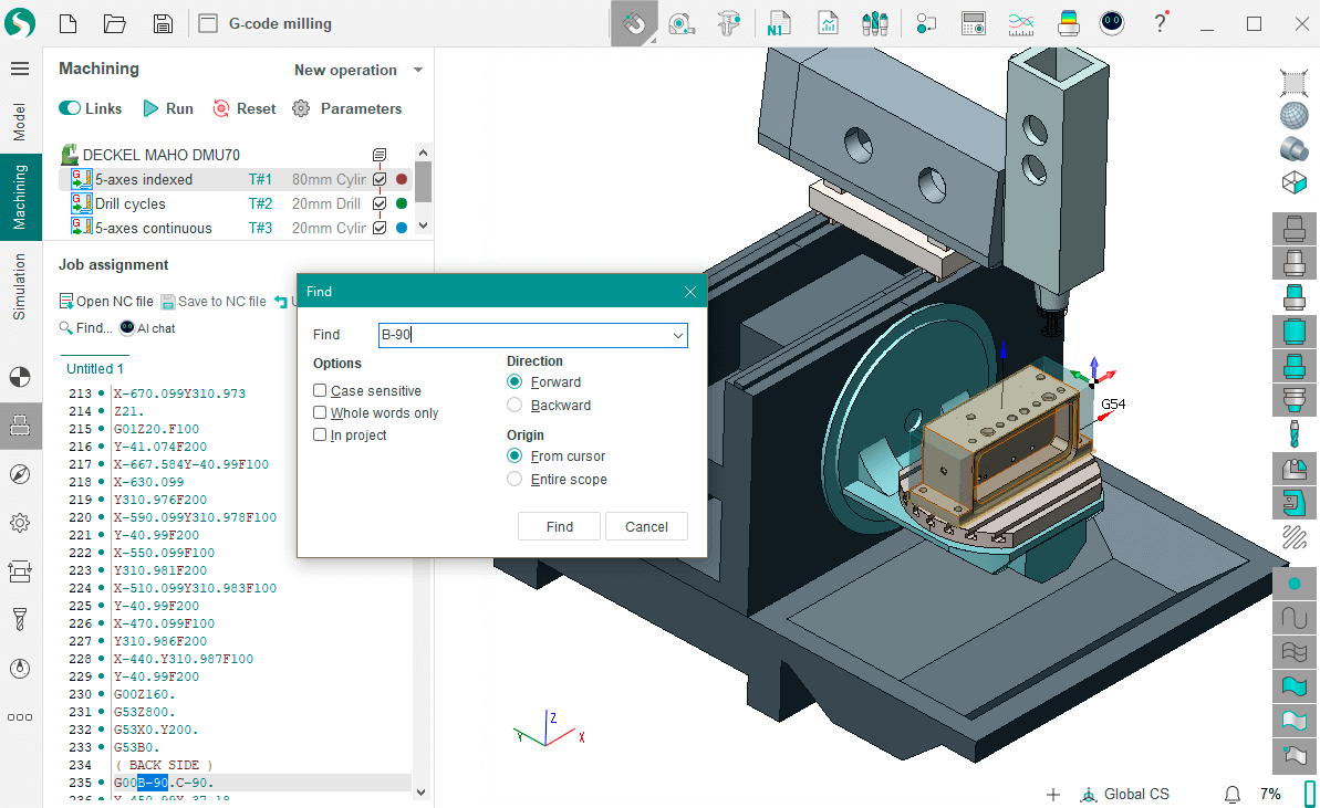
CAM Programming and G-Code Generation
Following DFM sign-off, our certified CNC programmers utilize Mastercam and Siemens NX CAM software to generate optimized toolpaths. The process includes:
Selection of certified tooling libraries matching Honyo’s ISO 9001-controlled inventory
Simulation of multi-axis motion (3-axis, 4-axis, 5-axis) with collision avoidance checks
Material-specific feedrate and spindle speed calculations based on our validated machining parameters database
Creation of machine-specific G-code with embedded probing cycles for in-process verification
All G-code undergoes a three-stage validation: software simulation (Vericut), dry-run verification on the target machine without stock, and first-article inspection against the original CAD model using our Zeiss CMM.
Production and Quality-Controlled Delivery
Approved G-code drives production on our HAAS, DMG MORI, and Makino CNC equipment, with real-time monitoring via MTConnect. Every part batch includes:
In-process inspections at critical stages using calibrated micrometers and optical comparators
Final first-article inspection report with dimensional data against all critical features
Material certification and RoHS compliance documentation where applicable
Completed parts undergo deburring, cleaning, and non-destructive testing as specified, followed by packaging in anti-static, shock-absorbent materials. Orders ship with full traceability documentation including G-code version, machine logs, and inspection reports, typically meeting quoted lead times of 5-15 business days for prototypes and low-volume production. This integrated workflow ensures G-code accuracy while maintaining full accountability from digital design to physical part delivery.
Start Your Project
For expert CNC G-code programming and precision manufacturing services, contact Susan Leo at [email protected]. Our advanced production facility in Shenzhen ensures high-accuracy, efficient processing for your prototyping and production needs. Trust Honyo Prototype for reliable, in-house CNC solutions backed by technical excellence.
🚀 Rapid Prototyping Estimator
Estimate rough cost index based on volume.