Contents
Manufacturing Insight: Cnc Format File
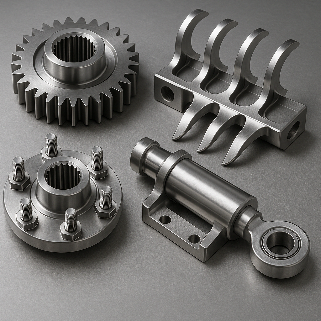
Precision CNC Machining Starts with the Right File Format
At Honyo Prototype, we deliver end-to-end CNC machining solutions engineered for uncompromising accuracy, speed, and repeatability across complex components. Our multi-axis milling and turning capabilities handle aluminum, steel, titanium, plastics, and exotic alloys with tolerances down to ±0.0002 inches, supported by rigorous in-process metrology and material traceability. To ensure seamless transition from design to physical part, submitting your geometry in a compatible CNC format file is the critical first step. Native formats like STEP, IGES, or Parasolid minimize data loss, prevent feature misinterpretation, and eliminate costly rework—directly impacting manufacturability and lead time.
Honyo’s technical team validates every file against machine kinematics, tooling constraints, and material behavior to guarantee first-pass success. By standardizing on these formats, you leverage our full process control—from automated toolpath generation to real-time adaptive machining—without delays from geometry repair or clarification loops. This precision in data handoff is why 92% of qualified quotes proceed to production without revision.
Upload your STEP, IGES, or native CAD file today to activate Honyo’s Online Instant Quote system. Receive a detailed manufacturability assessment, lead time, and cost breakdown in under 2 hours—no registration or sales calls required. Accelerate your prototyping or low-volume production with CNC machining engineered for results, not revisions.
Technical Capabilities
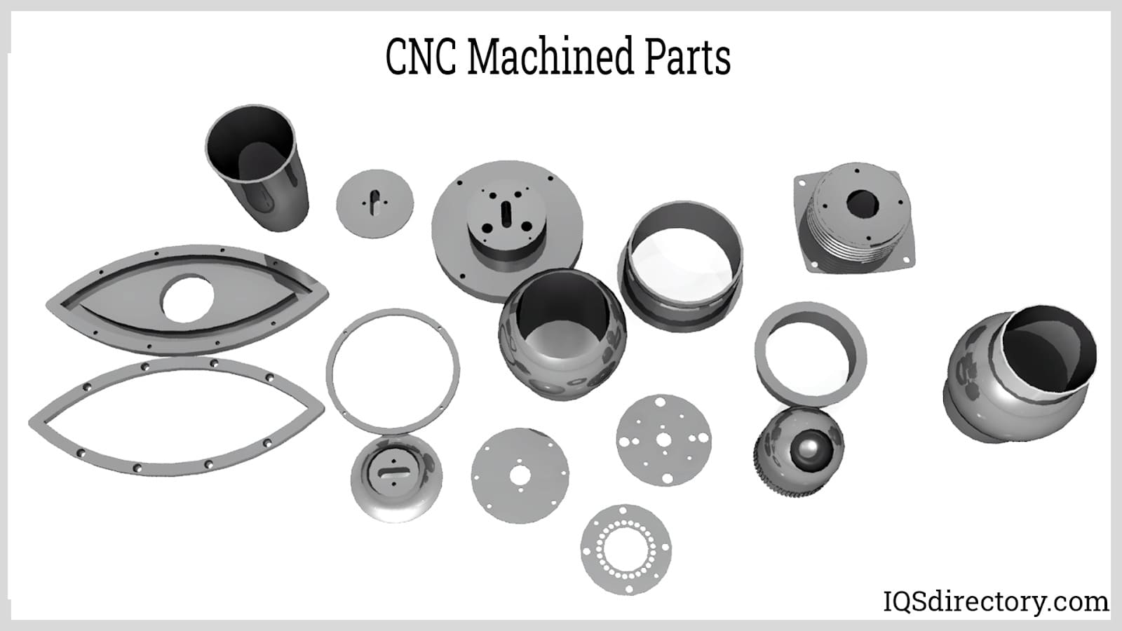
The term “CNC format file” typically refers to the digital programming format used to control CNC machines, most commonly G-code (ISO 6983), though it may also include native CAM software files (e.g., .NC, .EIA, .TXT) or CAD formats (e.g., STEP, IGES) that are translated into machine-specific code. For precision machining applications such as 3-, 4-, and 5-axis milling and turning with tight tolerances, the CNC program must accurately define toolpaths, spindle speeds, feed rates, and coordinate systems to ensure part accuracy and surface finish.
Below is a technical summary of CNC programming and machining specifications relevant to 3/4/5-axis milling and turning processes, with emphasis on tight tolerance work and common engineering materials.
| Parameter | Description |
|---|---|
| CNC File Format | G-code (ISO 6983 standard), typically generated from CAM software (e.g., Mastercam, Siemens NX, Fusion 360). Files are saved as .NC, .EIA, or .TXT. Pre-processing includes toolpath simulation and G-code verification to prevent collisions and ensure accuracy. |
| Axis Configuration | 3-Axis: X, Y, Z linear motion for prismatic parts. 4-Axis: Adds A (rotary around X) for indexing features. 5-Axis: Adds A and B (or C) for full simultaneous multi-axis motion, enabling complex geometries, reduced setups, and improved tool access. |
| Tolerance Capability | Typical tight tolerances: ±0.005 mm (±0.0002″) for critical dimensions. Achievable via high-precision CNC machines (±0.002 mm repeatability), thermal compensation, and in-process probing. Geometric tolerances (GD&T) such as position, flatness, and runout are strictly controlled. |
| Surface Finish | Milling: Ra 0.8–3.2 µm (typical), down to Ra 0.4 µm with fine finishing passes. Turning: Ra 0.4–1.6 µm. Achieved through optimized feeds/speeds, sharp tooling, and vibration control. |
| Materials – Aluminum | Common grades: 6061-T6, 7075-T6. Machinability: Excellent. CNC considerations: High thermal conductivity requires effective chip evacuation and coolant; prone to work hardening if feeds are too low. Tight tolerance parts often stress-relieved pre-machining. |
| Materials – Steel | Grades: 4140, 1018, A2, D2 (tool steel). Machinability: Moderate to difficult depending on hardness. CNC considerations: Lower cutting speeds, rigid setups, and carbide tooling required. For tight tolerances, slow ramp-down feeds near final dimensions and use of through-spindle coolant improve accuracy. |
| Materials – ABS | Thermoplastic polymer. CNC considerations: Low melting point requires sharp tools and high-speed, low-feed strategies to prevent melting or burring. Fixturing must avoid distortion. Tolerances up to ±0.05 mm achievable with controlled parameters. |
| Materials – Nylon | Polyamide (e.g., PA6, PA66). CNC considerations: Hygroscopic—must be dry before machining. Low stiffness requires light clamping and high-speed cutting to minimize deflection. Dimensional stability is critical; post-machining conditioning may be needed for tight tolerance applications. |
| Tooling Requirements | Carbide end mills, inserts, and drills for metals; polycrystalline diamond (PCD) or high-speed steel (HSS) for plastics. Tool presetting and runout < 0.003 mm ensure precision. Adaptive toolpath strategies used in 5-axis milling to maintain constant engagement. |
| Machine Requirements | High-rigidity CNC machining centers with linear scales (for closed-loop positioning), spindle speeds up to 20,000 RPM (for finishing), and thermal stability systems. Turning centers with live tooling support for mill-turn operations. |
| Verification & Metrology | First-article inspection (FAI) using CMM, optical comparators, or laser scanning. In-process probing used for tool wear compensation and setup validation. CAM software must support tolerance-driven toolpath optimization. |
This technical framework ensures that CNC-machined components meet stringent dimensional and surface quality requirements across diverse materials and complex geometries.
From CAD to Part: The Process
Honyo Prototype employs a rigorously defined and integrated workflow for CNC machining projects, designed to maximize efficiency, quality, and transparency from initial inquiry through final delivery. This structured process ensures manufacturability is validated early while providing clients with rapid feedback and predictable outcomes. The sequence begins with the CAD File Upload phase, where clients submit their 3D model through our secure online portal. We strongly recommend native CAD formats or industry-standard neutral formats to preserve critical geometric and feature data essential for accurate quoting and machining. Accepted formats and their implications are detailed below.
| CAD Format Type | Supported Formats | Recommendation Level | Primary Reason for Preference |
|---|---|---|---|
| Native CAD | SOLIDWORKS (.sldprt, .sldasm), Creo (.prt, .asm), NX (.prt), CATIA (.CATPart, .CATProduct), Inventor (.ipt, .iam) | Preferred | Retains full feature history, parameters, and metadata, enabling optimal DFM analysis and program generation |
| Neutral Exchange | STEP (.stp, .step), IGES (.igs, .iges) | Highly Recommended | Preserves precise geometry and topology without feature tree; widely compatible and reliable for CNC programming |
| Mesh Formats | STL (.stl), OBJ (.obj) | Not Recommended for CNC | Lacks precise geometry; suitable only for basic visual prototypes, not functional CNC parts |
Following successful upload, the AI-Powered Quoting Engine immediately processes the geometry. This system performs automated feature recognition, material and volume analysis, and machine time estimation based on Honyo’s extensive historical production database and real-time machine capability parameters. The AI generates a preliminary quote within minutes, including base pricing, estimated lead time, and initial manufacturability flags. Crucially, this is not a final quote; it serves as a rapid first-pass assessment to identify potential high-cost drivers or fundamental feasibility issues before human engineering review.
The Design for Manufacturability (DFM) Review phase is where Honyo’s engineering expertise becomes central. Our certified manufacturing engineers conduct a thorough technical assessment of the AI output and the original CAD model. This involves verifying dimensional tolerances against machine capabilities, analyzing feature complexity for optimal toolpath strategies, checking wall thicknesses and aspect ratios, identifying potential fixturing challenges, and assessing material suitability. We proactively engage clients with specific, actionable recommendations for design optimization—such as adjusting radii, modifying draft angles, or consolidating features—to reduce cost, improve part integrity, and accelerate production. Client approval of the DFM report and final quote is required before proceeding, ensuring complete alignment on specifications and expectations.
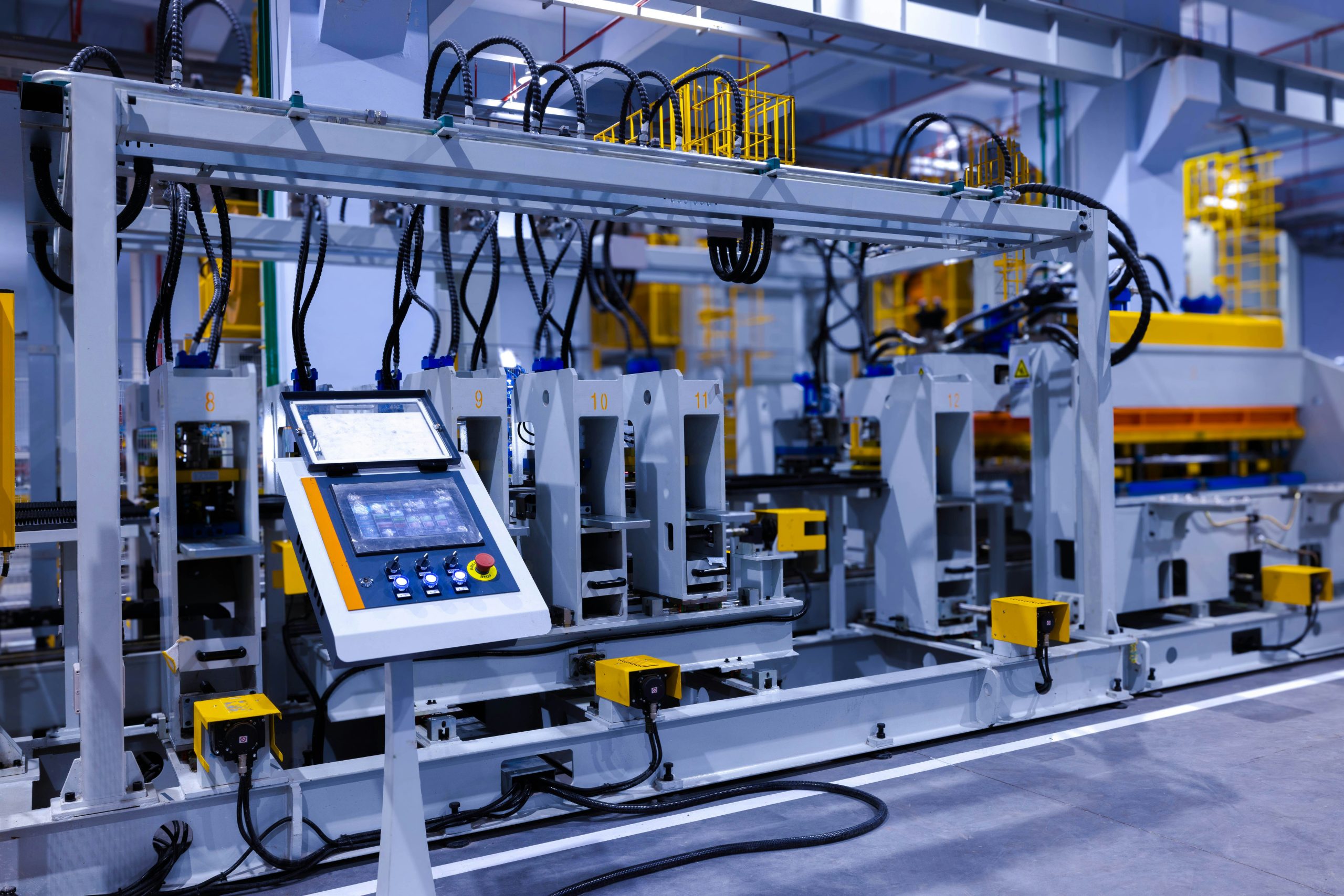
Upon DFM sign-off, the project enters CNC Production. Our CAM team generates optimized, machine-specific toolpaths using industry-leading software (Mastercam, Fusion 360, PowerMill), rigorously simulating all operations to prevent collisions and verify accuracy. Parts are machined on our certified Haas, DMG MORI, and Makino equipment, with in-process inspections conducted at critical stages using calibrated CMMs, optical comparators, and surface roughness testers. All production adheres strictly to ISO 9001:2015 quality management protocols, with full material traceability and documented process controls. Complex assemblies undergo functional testing where specified.
The final Delivery and Documentation phase ensures seamless client integration. Completed parts undergo final first-article inspection against the approved drawing, with a comprehensive inspection report (including CMM data where applicable) provided digitally. Parts are carefully packaged using anti-corrosion materials and shipped via client-preferred carriers with real-time tracking. All project data—including the approved DFM report, CAM files, inspection documentation, and material certifications—is archived in the client’s secure portal for future reference or repeat orders. This closed-loop process guarantees that every CNC project delivered meets Honyo’s uncompromising standards for precision, quality, and on-time performance.
Start Your Project
Need your CNC format file processed quickly and accurately? Contact Susan Leo at [email protected] to discuss your project requirements. With our advanced manufacturing capabilities and quality control, your prototypes are in trusted hands.
Our factory is located in Shenzhen, China — a hub for precision manufacturing and rapid production. Whether you’re sending STEP, IGES, X_T, or native CAD files, we support all major CNC-compatible formats and ensure seamless processing from design to delivery.
Reach out today to get a fast quote and technical consultation.
🚀 Rapid Prototyping Estimator
Estimate rough cost index based on volume.