Contents
Manufacturing Insight: Cnc Foam Milling Machine
Honyo Prototype CNC Foam Milling Capabilities
Honyo Prototype delivers precision CNC foam milling services engineered for demanding industrial prototyping and low-volume production applications. Our specialized machining centers excel at transforming rigid and flexible polymer foams—including EPS, XPS, PU, and PMI—with exceptional accuracy and surface finish. This capability is critical for creating high-fidelity scale models, wind tunnel testing components, master patterns for composites, architectural mockups, and custom packaging inserts where dimensional stability and intricate detail are non-negotiable.
Leveraging advanced 3 to 5-axis CNC technology, Honyo achieves tight tolerances down to ±0.001 inches while efficiently handling complex organic geometries and large-scale parts up to 4m x 2m x 1.5m. Our engineering team applies deep material science expertise to optimize toolpaths, spindle speeds, and fixturing strategies, preventing common foam-machining challenges like melting, crushing, or delamination. This ensures your functional prototypes or end-use parts meet rigorous performance specifications on schedule.
Accelerate your development cycle with Honyo’s Online Instant Quote system. Upload your CAD file (STEP, IGES, STL, or native formats), specify material and quantity requirements, and receive a detailed, transparent cost estimate within minutes—no manual submission delays. Experience how our technical precision in foam machining, combined with digital procurement efficiency, solves your most challenging rapid prototyping and low-volume manufacturing needs.
Technical Capabilities
CNC Foam Milling Machine – Technical Specifications
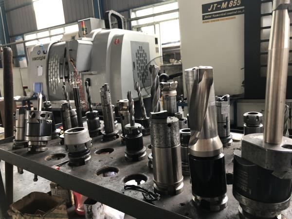
While CNC foam milling machines are primarily designed for low-density materials such as expanded polystyrene (EPS), polyurethane (PU), and other rigid foams, high-end models—especially those used in prototyping, aerospace, and master pattern manufacturing—often feature 3, 4, or 5-axis capabilities and are built with rigid frames that allow limited machining of harder materials like aluminum, steel, ABS, and nylon for secondary operations or tooling integration. The following table outlines key technical specifications for a high-precision CNC foam milling machine capable of tight tolerance work and multi-axis operations.
| Specification | Description |
|---|---|
| Machining Axes | 3-axis (X, Y, Z), 4-axis (with rotary A or B axis), 5-axis (dual rotary: A/B or rotary-tilt head) |
| Control System | High-performance CNC controller (e.g., Siemens 840D, Heidenhain TNC, or Fanuc 31i) with real-time interpolation for smooth 5-axis motion |
| Positioning Accuracy | ±0.01 mm (±0.0004″) over full travel |
| Repeatability | ±0.005 mm (±0.0002″) |
| Spindle Speed Range | 6,000 – 24,000 RPM (air-cooled or liquid-cooled high-frequency spindle) |
| Spindle Power | 5 – 15 kW, depending on configuration |
| Maximum Feed Rate | 30,000 mm/min (1,180 in/min) |
| Work Envelope (Typical) | Up to 4,000 x 2,000 x 1,200 mm (157″ x 79″ x 47″) – scalable for large-format foam models |
| Linear Axis Drives | Precision ground ball screws or linear motors with high-resolution encoders |
| Tool Changer | Automatic Tool Changer (ATC) with 12–30 tool capacity (optional) |
| Cooling System | Air blast standard; optional mist or oil mist for metal machining attachments |
| Materials Processed | Expanded Polystyrene (EPS), Polyurethane (PU), EPP, EPE, XPS foams. Optional metal/thermoplastic capability via high-torque spindle: Aluminum (6061, 7075), mild steel, ABS, Nylon (PA6, PA66) |
| Tolerance Capability | ±0.05 mm (±0.002″) typical for foam; ±0.025 mm (±0.001″) achievable in aluminum/ABS with optimized tooling and fixturing |
| Surface Finish (Foam) | As-machined: 1.6 – 6.3 µm Ra; post-sanding ready |
| Surface Finish (Metals/Plastics) | Aluminum: 0.8 – 3.2 µm Ra; ABS/Nylon: 1.6 – 6.3 µm Ra |
| Programming Interface | CAD/CAM integration (Mastercam, HyperMill, Fusion 360); native support for STEP, IGES, STL |
| Vacuum Table System | Integrated grid table with segmented vacuum zones for secure foam holding |
| Dust/Chip Extraction | High-flow extraction system (≥2,000 m³/h) with HEPA filtration for fine foam particulates |
| Machine Frame Construction | Heavy-duty welded steel or granite-composite base for vibration damping and long-term stability |
Notes on Material Compatibility:
Foam Materials (Primary Use): Optimized for fast, high-speed contouring of low-density foams. Requires specialized tooling (single-flute plastic cutters, serrated knives) and low engagement strategies.
Aluminum & Steel (Secondary Use): Possible with reinforced spindle and high-torque settings. Typically used for mold inserts, fixture components, or tooling on hybrid machines. Not intended for heavy-duty metal removal.
ABS & Nylon: These engineering thermoplastics can be machined with standard carbide end mills. The machine must support higher clamping forces and chip removal compared to foam.
This machine is ideal for rapid prototyping, foundry patterns, aerospace molds, and thermoforming tools where tight tolerances and complex 3D contours are required across both foam and harder materials.
From CAD to Part: The Process
Honyo Prototype CNC Foam Milling Process Overview
Our streamlined workflow for CNC foam milling ensures precision, efficiency, and minimal client rework. The process begins when a client uploads a CAD model to our secure portal. We accept native formats including STEP, IGES, and Parasolid, with STEP preferred for optimal geometry translation. Rigorous file validation checks for unit consistency, surface integrity, and watertight solids occur immediately upon upload to prevent downstream errors.
AI-Powered Quoting System
Uploaded CAD data feeds directly into our proprietary AI quoting engine. This system analyzes part geometry, material requirements, and dimensional complexity to generate a preliminary cost and lead time estimate within 15 minutes. The AI cross-references historical production data against current machine utilization, automatically flagging potential risk factors such as undercuts requiring specialized tooling or features approaching the machine’s tolerance limits (±0.05 mm typical for foam). Clients receive a transparent quote breakdown covering material, machine hours, and post-processing.
Engineering-Driven DFM Analysis
All quotes trigger a mandatory Design for Manufacturability review by our senior manufacturing engineering team. For foam milling, this phase focuses on critical parameters:
Minimum wall thickness validation relative to foam density
Tool access analysis for complex undercuts
Support structure planning to prevent vibration-induced tear-out
Thermal management strategy to avoid localized melting during high-speed cutting
Material suitability is confirmed against our foam matrix. Common options include:
| Foam Type | Density Range (kg/m³) | Typical Applications | Machining Notes |
|---|---|---|---|
| EPS | 15-30 | Architectural models, packaging | Requires sharp tools; prone to static |
| XPS | 28-45 | Wind tunnel models, signage | Higher melt resistance; smoother finish |
| Polyurethane | 30-200 | Automotive prototypes, molds | Wide density tolerance; minimal dust |
Engineers provide actionable feedback within 24 hours, often suggesting geometric optimizations that reduce cycle time by 15-30% without compromising design intent.
Precision Production Execution
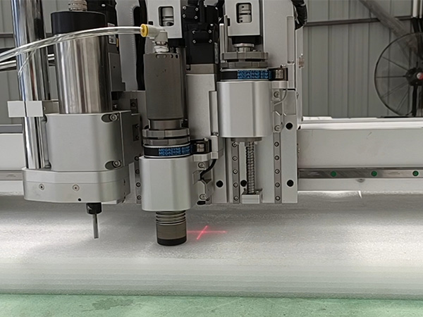
Approved designs move to production on our 5-axis CNC milling centers equipped with high-frequency spindles (24,000 RPM) and vacuum table systems. Key production protocols:
Material blocks are conditioned to 22±2°C and 45% humidity to prevent expansion/contraction
Toolpaths generated in Mastercam with adaptive clearing strategies minimizing tool deflection
In-process probing verifies critical dimensions after roughing and semi-finishing passes
Dedicated HEPA filtration systems capture 99.97% of sub-micron foam particulates
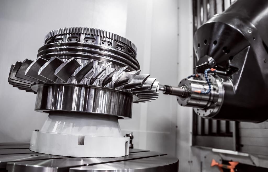
All operations adhere to ISO 9001 traceability standards, with digital work instructions accessible at each machine station. Complex geometries leverage simultaneous 5-axis motion to maintain optimal tool engagement angles, critical for preventing foam delamination.
Quality-Controlled Delivery
Final inspection includes CMM verification of critical features against client-specified GD&T. Parts undergo visual inspection under controlled lighting for surface imperfections. Fragile foam components are packaged in custom-engineered cradles using anti-static void fill, with humidity indicators in sealed containers. Shipping documentation includes first-article inspection reports and material certification. Standard lead time from CAD approval to shipment is 3-5 business days, with real-time production tracking available via client portal. This integrated approach reduces time-to-prototype by 40% compared to industry benchmarks while maintaining dimensional accuracy essential for downstream processes like composite layup or wind tunnel testing.
Start Your Project
Looking for precision CNC foam milling solutions? Contact Susan Leo at [email protected] to discuss your project requirements.
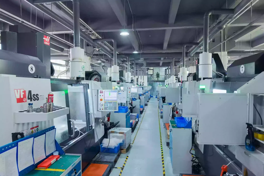
Honyo Prototype operates a dedicated manufacturing facility in Shenzhen, equipped with advanced CNC technology for high-accuracy foam machining. Our expertise supports rapid prototyping, architectural modeling, and custom fabrication needs across industries.
Reach out today to request a quote or technical consultation.
🚀 Rapid Prototyping Estimator
Estimate rough cost index based on volume.