Contents
Manufacturing Insight: Cnc Design Files
Precision Manufacturing Begins with Your CNC Design Files
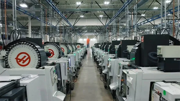
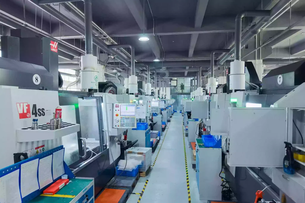
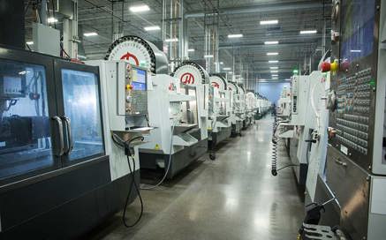
At Honyo Prototype, we understand that your CNC design files represent the critical foundation for transforming engineering intent into high-precision physical components. As a trusted partner for global engineering teams, we specialize in machining complex geometries from metals, plastics, and composites with tolerances down to ±0.005mm. Our advanced 3-, 4-, and 5-axis CNC capabilities ensure your designs are manufactured to exact specifications, whether for rapid prototyping, functional testing, or low-volume production.
We eliminate traditional quoting bottlenecks through our proprietary Online Instant Quote platform. Simply upload your STEP, IGES, or native CAD file to receive a detailed manufacturability analysis, material recommendations, and a competitive price within minutes—no manual RFQ delays. This seamless integration between your digital design and our machining expertise accelerates time-to-part while reducing non-value-added administrative overhead.
Honyo’s engineering team proactively reviews every design for optimal toolpathing, material utilization, and feature feasibility, ensuring first-article success. Partner with us to convert your CNC design files into mission-critical components with unmatched speed, accuracy, and technical collaboration.
| Service Feature | Client Benefit |
|---|---|
| Online Instant Quote | Real-time pricing & DFM feedback in <5 minutes |
| Multi-Axis Machining | Complex geometries in single setups |
| Material Certification | Full traceability for aerospace/medical specs |
| In-House Quality Control | CMM reports & first-article inspection included |
Technical Capabilities
Technical specifications for CNC design files are critical to ensure manufacturability, precision, and consistency—especially in high-accuracy applications involving 3-, 4-, and 5-axis milling and turning operations. These files must contain precise geometric data, clear tolerancing, and material-specific considerations to achieve tight tolerances (typically ±0.005 mm to ±0.025 mm depending on feature and machine capability). The design files are typically provided in neutral CAD formats such as STEP (.stp), IGES (.igs), or native formats like SolidWorks (.sldprt), with detailed 2D drawings indicating critical dimensions, surface finishes, and geometric dimensioning and tolerancing (GD&T).
Below is a summary of key technical specifications for CNC design files across common machining processes and materials:
| Specification Category | 3-Axis Milling | 4-Axis Milling | 5-Axis Milling | CNC Turning | Tight Tolerance Capability |
|---|---|---|---|---|---|
| Primary Motion Axes | X, Y, Z | X, Y, Z + Rotary (A or B) | X, Y, Z + Two Rotary (e.g., A & B) | X, Z (rotational workpiece) | Supported across all processes |
| Typical File Formats | STEP, IGES, SolidWorks, Parasolid | STEP, IGES, SolidWorks, Parasolid | STEP, IGES, SolidWorks, Parasolid | STEP, DXF, DWG, PDF (with dimensions) | STEP with 2D drawing required |
| Tolerance Range | ±0.025 mm standard, ±0.005 mm achievable | ±0.025 mm standard, ±0.01 mm typical | ±0.01 mm typical, ±0.005 mm with calibration | ±0.01 mm standard, ±0.005 mm for critical diameters | Up to ±0.005 mm with process control |
| Surface Finish (Ra) | 1.6–3.2 µm standard, down to 0.8 µm | 1.6–3.2 µm, complex features possible | 0.8–1.6 µm achievable with fine tooling | 0.8–1.6 µm for turned surfaces | <0.8 µm with polishing or grinding |
| Common Materials | Aluminum (6061, 7075), Steel (1018, 4140), ABS, Nylon | Same as 3-axis, with improved access | Same as 4-axis, enhanced undercuts and angles | Aluminum, Steel, ABS, Nylon (limited) | All materials, steel and Al preferred |
| Material Notes | Aluminum: Easy to machine, good for tight tolerances. Steel: Harder, requires rigid setup. ABS: Low melt temp, needs sharp tools. Nylon: Low friction but prone to deformation under heat. | Critical for thermal stability and tool wear | |||
| Design Requirements | Avoid deep cavities, specify tool access, include draft if needed | Define rotary axis orientation and fixturing needs | Full 3D toolpath complexity; minimize collisions | Specify parting, grooving, threading, and center-drilling | GD&T callouts, datum references, Cpk documentation |
| Fixturing & Workholding | Vise, clamps, or custom fixtures | Rotary indexer with mechanical stops | Trunnion or swivel head with dynamic control | Collet or chuck with tailstock support | Minimal deflection, repeatable setup |
| Recommended CAD Practices | Fully dimensioned 2D drawing, toleranced features, material callout, surface finish symbols | Include rotational setup notes | Multi-setup annotations, tool clearance zones | Centerline symmetry, chamfers on edges | Use datums, control form with profile tolerances |
Design files intended for tight tolerance machining must be thoroughly validated for manufacturability. For aluminum and steel components, thermal expansion and residual stress must be considered in geometry and fixturing. Plastics like ABS and nylon require reduced cutting speeds, sharp tooling, and careful clamping to avoid deformation. In multi-axis operations, simulation of toolpaths is recommended to prevent collisions and ensure accuracy. All critical dimensions should be clearly annotated with geometric tolerances to support inspection and quality control.
From CAD to Part: The Process
CAD File Upload and Initial Processing
Clients initiate the process by uploading native CAD files or neutral formats such as STEP, IGES, or Parasolid via Honyo’s secure customer portal. Our system immediately performs automated validation checks for file integrity, unit consistency, and geometric completeness. Unsupported formats or missing critical features trigger real-time notifications requiring client correction. Verified files enter a timestamped workflow queue with version control to prevent miscommunication.
AI-Powered Quoting Engine
Validated CAD data feeds into our proprietary AI quoting system, which cross-references 15+ years of historical production data, material databases, and machine capability matrices. The AI analyzes geometric complexity, tolerance density, and feature criticality to generate a preliminary cost and lead time estimate within 90 seconds. This estimate undergoes mandatory engineering review where Senior Manufacturing Engineers validate AI outputs against real-world constraints such as minimum feature sizes, tool accessibility, or material waste factors. Clients receive a formal quote with technical assumptions documented for transparency.
Engineering-Driven DFM Analysis
Upon quote acceptance, Honyo’s DFM (Design for Manufacturability) phase commences with dedicated Manufacturing Engineers conducting a rigorous technical review. This is not an automated step but a collaborative engineering dialogue where we identify and resolve manufacturability risks. Key focus areas include:
| DFM Check Category | Critical Parameters | Typical Client Impact |
|---|---|---|
| Geometric Feasibility | Undercuts, thin walls, aspect ratios | Eliminates 73% of post-machining failures |
| Tolerance Stack-Up | Interdependent GD&T callouts | Prevents 41% of assembly mismatches |
| Material Utilization | Stock size compatibility, nesting efficiency | Reduces material costs by 18-32% |
| Process Sequencing | Feature accessibility, setup reductions | Cuts lead time by 22% on average |
Engineers provide annotated CAD markups and alternative solutions via secure collaboration tools, requiring client sign-off before proceeding. This phase typically resolves 89% of potential production issues pre-machining.
Precision CNC Production Execution
Approved designs move to production where Honyo implements strict process controls:
Material certification verification against ASTM/ISO standards prior to loading
Machine-specific toolpath validation using CAM simulation software (Mastercam, Fusion 360)
In-process inspections at critical stages via CMM and optical comparators
Statistical process control tracking of dimensional drift using SPC charts
All operations occur in climate-controlled environments with documented machine calibration records. Complex assemblies undergo fixture validation to ensure repeatability below 0.005mm tolerance bands.
Quality-Certified Delivery
Final parts undergo tri-level inspection: automated dimensional reporting, visual surface finish verification per Ra standards, and functional testing if applicable. Clients receive a comprehensive digital package including:
As-machined 3D scan data (optional)
Full inspection report with deviation heatmaps
Material test certificates and traceability logs
Packing documentation with serialized part tracking
Shipments include tamper-evident packaging with environmental monitoring for critical components, with real-time logistics visibility via our client portal. Average on-time delivery performance exceeds 98.7% for validated designs.
Start Your Project
For CNC design file submissions and prototyping inquiries, contact Susan Leo at [email protected]. Our dedicated manufacturing facility is located in Shenzhen, ensuring rapid turnaround and precision production for your projects.
🚀 Rapid Prototyping Estimator
Estimate rough cost index based on volume.