Contents
Manufacturing Insight: Cnc Cad/Cam
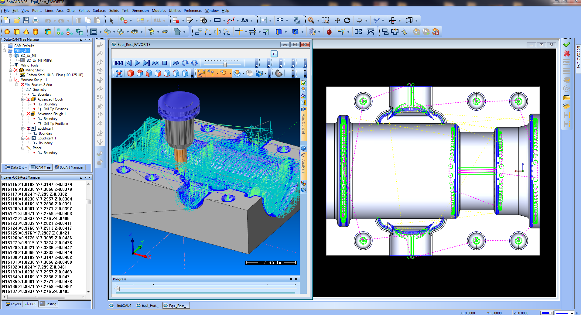
Precision CNC Machining Powered by Integrated CAD/CAM at Honyo Prototype
At Honyo Prototype, we transform complex engineering designs into high-precision, production-ready components through our advanced CNC machining services, fully integrated with industry-leading CAD/CAM workflows. Our engineering-driven approach ensures seamless transition from digital model to physical part, eliminating common translation errors and accelerating time-to-market for prototypes and low-volume production runs. By leveraging sophisticated CAD/CAM software, we optimize toolpaths, material utilization, and machining strategies for every project—whether machining intricate aerospace fixtures, medical device housings, or automotive prototypes—guaranteeing consistent accuracy down to ±0.0002 inches and superior surface finishes.
Our commitment to operational excellence is matched by a client-centric digital experience. Requesting a quote is effortless with our Online Instant Quote system: simply upload your 3D CAD file (STEP, IGES, Parasolid), specify materials, tolerances, and quantities, and receive a detailed, transparent cost estimate within minutes—no manual back-and-forth or delays. This real-time capability empowers engineering teams to iterate rapidly, validate manufacturability early, and maintain project momentum without sacrificing the rigorous quality standards Honyo Prototype delivers across all CNC milling, turning, and multi-axis operations. Partner with us to convert design intent into flawless metal and plastic components, backed by engineering expertise and digital efficiency.
Technical Capabilities
CNC CAD/CAM Technical Specifications for 3/4/5-Axis Milling and Turning – Focus on Tight Tolerance Machining
The following table outlines key technical specifications and capabilities for CNC machining processes utilizing CAD/CAM software, with emphasis on 3-axis, 4-axis, and 5-axis milling, CNC turning, and the ability to achieve tight tolerances. Materials include Aluminum, Steel, ABS, and Nylon—commonly used in precision prototyping and production at Honyo Prototype.
| Parameter | 3-Axis Milling | 4-Axis Milling | 5-Axis Milling | CNC Turning |
|---|---|---|---|---|
| Motion Axes | X, Y, Z | X, Y, Z, A (rotary around X) | X, Y, Z, A/B or A/C | X, Z (with optional C-axis) |
| Typical Tolerance | ±0.005 mm (±0.0002″) | ±0.005 mm (±0.0002″) | ±0.0025 mm (±0.0001″) | ±0.005 mm (±0.0002″) |
| Surface Finish (Ra) | 0.8 – 3.2 µm | 0.8 – 1.6 µm | 0.4 – 1.6 µm | 0.8 – 1.6 µm |
| Max Material Removal Rate | High | Medium-High | Medium (due to precision) | High (for cylindrical parts) |
| CAD/CAM Software Support | Full 3D modeling, toolpath simulation, G-code generation (e.g., Fusion 360, Mastercam, Siemens NX) | Indexed and continuous 4-axis toolpaths | Simultaneous 5-axis toolpathing, collision detection, high-precision simulation | Turn-mill programming, multi-axis live tooling support |
| Common Materials | Aluminum, Steel, ABS, Nylon | Aluminum, Steel, ABS, Nylon | Aluminum, Steel, ABS, Nylon | Aluminum, Steel, ABS, Nylon |
| Aluminum (6061, 7075) | Excellent machinability, high MRR, tight tolerance achievable | Suitable for complex features with indexing | Ideal for aerospace components requiring high precision | Standard for high-volume shafts, bushings |
| Steel (1018, 4140, Stainless 303/316) | Good with carbide tooling; slower speeds | Requires rigid setup; coolant recommended | High precision achievable with proper tooling and thermal control | Common for high-strength shafts and fittings |
| ABS | Easy to machine; low melting point; sharp tools required | Suitable for prototypes with undercuts | Used in low-stress, high-detail enclosures | Rare; used for custom plastic fittings |
| Nylon (6, 66, GF40) | Requires sharp tools and controlled feed; prone to burring | Good for wear-resistant components | Used in precision gears and bushings | Common for low-friction rotating parts |
| Fixturing Complexity | Low (standard vices) | Medium (rotary indexer needed) | High (custom fixtures, alignment critical) | Low-Medium (chucks, collets) |
| Applications | Flat surfaces, pockets, holes | Impellers, turbine blades, parts with angled features | Aerospace manifolds, medical implants, complex molds | Shafts, pins, threaded components |
Notes on Tight Tolerance Machining:
Achieving tolerances tighter than ±0.005 mm requires thermal stability, high-precision spindles (≤ 2 µm runout), and calibrated tool length compensation.
In-process probing and post-process CMM inspection are standard for verifying tight tolerance features.
Material stability (especially in Nylon and ABS) must be considered due to hygroscopic and thermal expansion characteristics.
At Honyo Prototype, advanced CAD/CAM workflows are integrated with high-rigidity CNC platforms to ensure repeatability and precision across all axis configurations and material types.
From CAD to Part: The Process
Honyo Prototype executes a streamlined CNC CAD/CAM workflow designed for precision, efficiency, and manufacturability, directly integrating engineering validation with production execution. Our process begins when a client uploads their native or neutral CAD file (STEP, IGES, Parasolid, SolidWorks, etc.) to our secure customer portal. This upload triggers immediate automated validation checks for file integrity, unit consistency, and geometric completeness, ensuring the dataset is production-ready before proceeding.
The validated CAD model enters our proprietary AI-powered quoting engine. This system analyzes geometric complexity, material requirements, tolerance specifications, and feature density against real-time machine availability, tooling libraries, and shop floor scheduling data. Unlike basic volume-based quoting tools, our AI cross-references historical production data from identical or similar geometries, generating a technically accurate cost and lead time estimate within minutes, including explicit justification for any complex feature surcharges.
Following client acceptance of the quote, the CAD model undergoes comprehensive Design for Manufacturability (DFM) analysis performed by our senior manufacturing engineering team. This is not an automated pass/fail check but a collaborative engineering review focused on optimizing the design for CNC machining efficiency while maintaining functional requirements. Key DFM activities include:
Verification of wall thicknesses, hole depths, and internal radii against minimum tooling capabilities
Assessment of feature accessibility for standard and custom tooling configurations
Identification of opportunities to reduce setups through geometric simplification
Tolerance stack-up analysis for critical interfaces
Material utilization optimization suggestions
We provide detailed DFM feedback with specific, actionable recommendations via annotated 3D markups and a formal report, enabling rapid design iteration. The table below illustrates the impact of our DFM process compared to standard industry practices.
| DFM Aspect | Standard Industry Practice | Honyo Prototype Practice | Client Benefit |
|---|---|---|---|
| Feedback Turnaround | 2-5 business days | < 24 business hours | Accelerated time-to-prototype |
| Revision Cycle Reduction | Typically 2-3 iterations | 85% of jobs resolved in ≤ 1 iteration | Lower NRE costs, faster validation |
| Tolerance Validation | Basic GD&T check only | Functional stack-up analysis with simulation | Higher first-pass yield, reduced scrap |
| Material Optimization | Rarely addressed | Standard practice with cost/benefit analysis | Lower material costs, sustainable output |
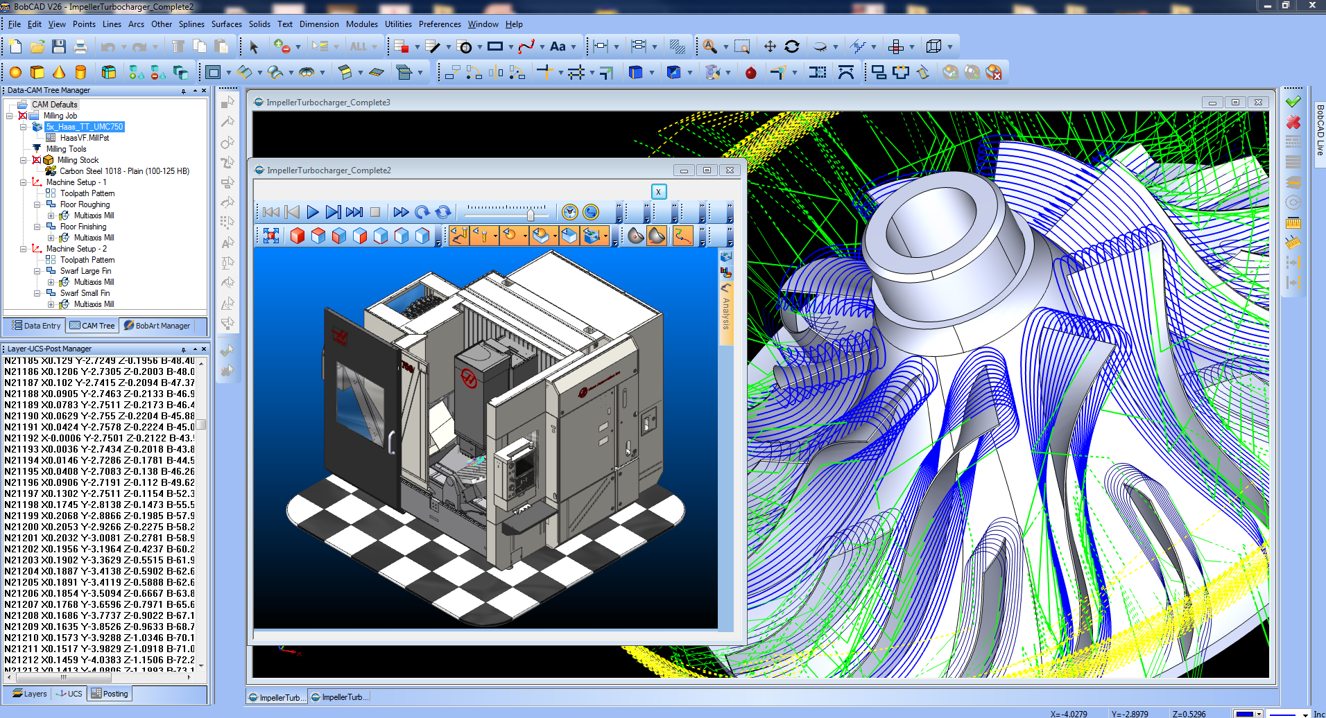
Upon DFM sign-off, our CAM team generates optimized machine toolpaths using Mastercam and Siemens NX, leveraging the validated CAD model and DFM insights. We apply dynamic milling strategies, high-efficiency roughing, and precision finishing toolpaths tailored to the specific machine platform (DMG MORI, Haas, Makino) and material. All programs undergo rigorous virtual machine simulation within CAM software and offline verification using GIBBS CAM Verify to eliminate collisions and ensure G-code integrity prior to shop floor deployment.
Production occurs in our climate-controlled facility on calibrated CNC equipment with documented maintenance records. We implement in-process inspections at critical stages using calibrated CMMs, optical comparators, and surface roughness testers, with full traceability of materials, tooling, and inspection data linked to the job. Final inspection documentation includes First Article Inspection reports per AS9102 or client-specified formats, with all critical dimensions verified against the original CAD model.
Delivery encompasses secure packaging meeting IPC-1601 standards, shipment tracking with real-time updates, and immediate electronic delivery of comprehensive quality documentation including dimensional reports, material certifications, and post-processing validation. Every shipped part includes a unique traceability code linking to its complete digital manufacturing record within our QMS, ensuring full compliance for regulated industries. This integrated process guarantees technically accurate quoting, manufacturable designs, and consistently high-quality CNC machined components delivered on schedule.
Start Your Project
Looking for precision CNC CAD/CAM services? Contact Susan Leo at [email protected] to discuss your project requirements. Our advanced manufacturing facility in Shenzhen delivers high-accuracy prototyping and production solutions tailored to your design and engineering needs.
🚀 Rapid Prototyping Estimator
Estimate rough cost index based on volume.