Contents
Manufacturing Insight: Cnc 3-Axis Milling Machine
Precision 3-Axis Milling Capabilities at Honyo Prototype
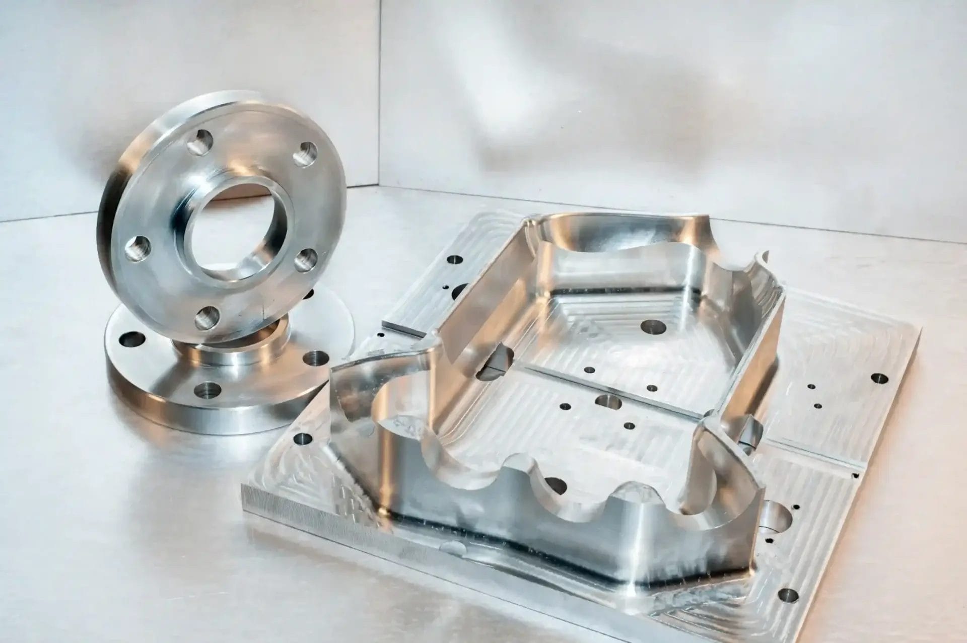
At Honyo Prototype, our CNC 3-axis milling services deliver the foundational precision and efficiency required for complex metal and plastic components in demanding industrial applications. As a core offering within our advanced CNC machining portfolio, our 3-axis milling centers excel at producing high-tolerance parts with exceptional repeatability, leveraging rigid machine platforms, optimized toolpath strategies, and stringent in-process inspection protocols. This capability is ideal for prismatic geometries, housings, brackets, and mechanical assemblies where consistent dimensional accuracy down to ±0.005 mm and superior surface finishes are non-negotiable.
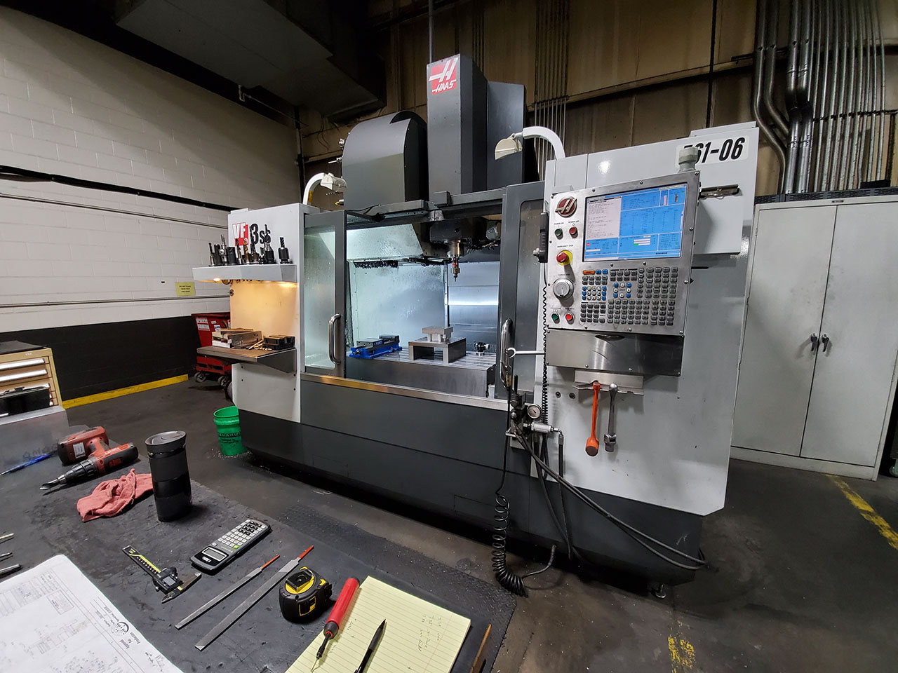
We integrate industry-standard Haas and DMG MORI equipment with proven CAM workflows to minimize cycle times while maintaining strict adherence to engineering specifications. Our engineering team collaborates closely with clients during design for manufacturability (DFM) reviews to eliminate costly iterations, ensuring optimal material utilization and process stability from prototype to low-volume production. Every component undergoes comprehensive first-article inspection with calibrated CMMs and metrology reports traceable to NIST standards, providing full quality assurance for aerospace, medical, and industrial clients.
Accelerate your project timeline with Honyo’s Online Instant Quote system. Simply upload your STEP or IGES file to receive a detailed manufacturability analysis and competitive pricing within hours—not days. This transparent, no-obligation platform eliminates quoting delays, giving engineers immediate insight into lead times, cost drivers, and actionable feedback for design optimization.
Material & Tolerance Reference
| Parameter | Specification Range |
|---|---|
| Max Work Envelope | 1000 x 600 x 500 mm |
| Typical Tolerance | ±0.005 mm (standard) |
| Surface Finish | Ra 0.8 µm (as machined) |
| Supported Materials | Aluminum 6061/7075, Steel 1018/4140, Stainless 303/316, Plastics (PEEK, Delrin) |
Leverage Honyo Prototype’s engineering rigor and streamlined quoting process to transform your designs into certified, production-ready components with unmatched speed and precision. Upload your design today for an instant technical and commercial assessment.
Technical Capabilities
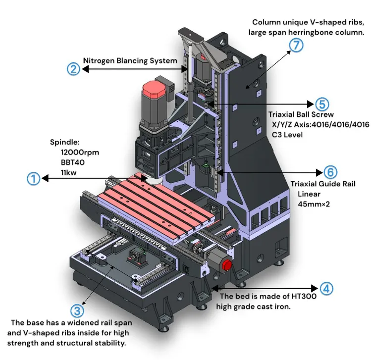
CNC 3-Axis Milling Machine – Technical Specifications Overview
While the query references 3/4/5-axis milling, the core subject is a 3-axis CNC milling machine. Below are the technical specifications relevant to 3-axis CNC milling, with context on capabilities for 4- and 5-axis upgrades, turning integration, tight tolerance performance, and material compatibility including aluminum, steel, ABS, and nylon.
| Specification | 3-Axis CNC Milling Machine | Notes on 4/5-Axis Upgrades | Turning Capability | Tight Tolerance Performance | Compatible Materials (Examples) |
|---|---|---|---|---|---|
| Axis Configuration | X, Y, Z linear axes only | 4-axis adds rotary A or B axis; 5-axis adds two rotary axes (e.g., A and C) for complex contouring | Not standard; requires mill-turn or dedicated lathe | Standard 3-axis: ±0.005 mm (±0.0002″) | Aluminum (6061, 7075), Steel (1018, 4140), ABS, Nylon (6, 66) |
| Positioning Accuracy | ±0.01 mm (±0.0004″) | ±0.005 mm (±0.0002″) achievable with high-end 5-axis systems | ±0.005 mm typical on integrated mill-turn | Can achieve ±0.0025 mm (±0.0001″) with thermal compensation and probing | All listed materials processable within tolerance bands |
| Repeatability | ±0.005 mm (±0.0002″) | ±0.002 mm possible on precision 5-axis machines | ±0.0025 mm on high-end turning centers | Critical for aerospace, medical, and precision tooling | Aluminum and ABS offer best repeatability due to low deformation |
| Spindle Speed Range | 8,000 – 24,000 RPM (standard); higher with high-speed options | 5-axis machines often feature higher RPM for fine finishes | 3,000 – 10,000 RPM typical for turning spindles | High spindle stability required for sub-±0.005 mm tolerances | Steel requires lower RPM; aluminum/ABS/Nylon allow higher speeds |
| Spindle Power | 7.5 – 15 kW | 10 – 20 kW in 5-axis high-torque configurations | 5 – 15 kW depending on workpiece size | Adequate power ensures minimal deflection during precision cuts | Steel demands higher spindle power vs. plastics |
| Tool Changer | Manual or automatic (ATC), 10–30 tool capacity | 30+ tool capacity common in 5-axis with pallet changers | Often integrated with turret (8–12 stations) | ATC reduces human error, supports multi-operation precision | Essential for unattended machining of mixed materials |
| Control System | Fanuc, Siemens, or Heidenhain-based | Advanced controls with RTCP (Rotational Tool Center Point) in 5-axis | Dual-spindle controls for mill-turn systems | Real-time error compensation improves tolerance control | All systems support material-specific toolpath optimization |
| Work Envelope (Typical) | 500 x 400 x 300 mm (X-Y-Z) | Larger envelopes in 5-axis (e.g., 1000 x 800 x 600 mm) | Diameter capacity: up to Ø400 mm | Smaller work volumes easier to thermally stabilize for tight tolerances | Larger parts may require fixturing compensation |
| Surface Finish (Ra) | 0.8 – 3.2 µm (typical) | <0.4 µm achievable with 5-axis finishing passes | <0.8 µm with fine turning and polishing | Critical for sealing surfaces and mating components | Nylon and ABS may require specialized tooling for smooth finish |
| Material Compatibility Notes | Aluminum: excellent; Steel: good; ABS: good; Nylon: fair | 5-axis allows undercuts and complex geometries in all materials | Turning ideal for cylindrical steel/aluminum parts | Plastics (ABS, Nylon) require optimized feeds/speeds to avoid melting | Use sharp carbide tools for plastics to minimize burring |
Summary Notes:
3-axis CNC milling machines are ideal for prismatic parts and offer strong precision for aluminum, steel, ABS, and nylon. For complex geometries requiring undercuts or angled features, upgrading to 4- or 5-axis configurations significantly enhances capability. Tight tolerances down to ±0.0025 mm are achievable with proper machine calibration, environmental control, and tooling. While 3-axis systems do not support turning, mill-turn hybrid machines combine both functionalities for complete machining. Material selection impacts spindle settings, tool life, and achievable surface finish—especially in thermoplastics like ABS and nylon, where heat buildup must be minimized.
From CAD to Part: The Process
Honyo Prototype CNC 3-Axis Milling Process Workflow
Our CNC 3-axis milling process integrates advanced automation with rigorous engineering oversight to ensure precision, efficiency, and manufacturability from initial design to final delivery. The workflow is structured to minimize lead times while maintaining strict quality control standards for B2B clients.
CAD File Upload and Validation
Clients initiate the process by uploading native or neutral format CAD files (STEP, IGES, Parasolid, native SOLIDWORKS, etc.) via our secure customer portal. The system performs immediate automated validation checks for file integrity, unit consistency, and basic geometric completeness. Files failing validation trigger an instant notification to the client specifying required corrections. Validated files proceed directly to the AI-powered quoting engine without manual intervention, ensuring a consistent starting point for all projects.
AI-Powered Quoting Engine
Honyo’s proprietary AI engine analyzes the validated CAD geometry against our extensive database of historical machine performance data, material properties, tooling costs, and real-time shop floor utilization metrics. The algorithm calculates precise machining time estimates by simulating toolpaths, accounting for material removal rates, spindle loads, and axis acceleration limits specific to our HAAS and DMG MORI 3-axis vertical machining centers. The generated quote includes detailed cost breakdowns for material, machine time, setup, and finishing operations, delivered within 2 business hours. Critical parameters influencing the quote are transparently presented to the client, such as estimated cycle time and primary cost drivers.
Engineering-Driven DFM Analysis
Every project undergoes a mandatory Design for Manufacturability (DFM) review led by our senior manufacturing engineering team. This phase combines automated analysis with human expertise to identify and resolve potential production issues. Key DFM focus areas include:
| DFM Parameter Category | Specific Checks Performed | Honyo Engineering Action |
|---|---|---|
| Geometric Feasibility | Minimum wall thickness, undercuts, deep cavities, thin features | Flag non-manufacturable geometries; propose redesign alternatives |
| Tolerancing Strategy | Tight tolerances on non-critical features, inconsistent datum schemes | Recommend tolerance relaxation or alternative inspection methods |
| Material Utilization | Excessive stock volume, inefficient nesting | Optimize stock size and part orientation to reduce material waste |
| Tool Access and Setup | Features requiring excessive setups or specialized tooling | Suggest design modifications to enable single-setup machining |
DFM feedback, including specific recommendations and potential cost/time impacts of design changes, is delivered within 4 business hours. Client approval of the DFM report is required before production commencement, ensuring alignment on manufacturability and cost.
Precision Production Execution
Approved orders move to production scheduling within our integrated ERP/MES system. Key production phases include:
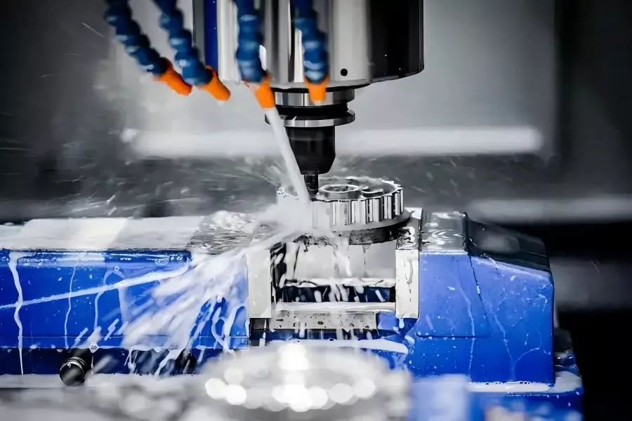
Material procurement from certified suppliers with full material test reports (MTRs) provided upon request. Machine setup using laser tool setters and Renishaw probes for precise work offset determination. Machining operations executed under strict environmental controls with real-time process monitoring of spindle load, vibration, and coolant conditions. In-process inspections at critical stages using calibrated CMMs or optical comparators to verify dimensional accuracy against the approved DFM specifications. Final first-article inspection (FAI) per AS9102 standards for aerospace clients or client-specified protocols, with full inspection reports available.
Quality-Controlled Delivery
Completed parts undergo final cleaning, deburring verification, and protective coating application as specified. Packaging is customized to part geometry and shipping requirements, utilizing static-dissipative materials for electronics components or corrosion-inhibiting VCI packaging for extended storage. All shipments include comprehensive documentation: traceable material certification, FAI report, process non-conformance records (if applicable), and digital as-built inspection data. Real-time shipment tracking is provided via our client portal, with delivery confirmation and POD documentation sent automatically upon carrier handoff. Standard lead time from DFM approval to delivery is 5-7 business days for single prototypes, scalable for low-volume production runs.
Start Your Project
Explore precision manufacturing with our CNC 3-axis milling machine, engineered for high accuracy and efficiency in prototyping and low-volume production. Built to meet tight tolerances and complex geometries, this machine delivers consistent results for a wide range of industrial applications.
Our facility in Shenzhen ensures rapid turnaround and strict quality control, supporting clients across industries with reliable, cost-effective machining solutions.
For inquiries or to request a quote, contact Susan Leo at [email protected]. Let’s build your next project with precision and speed.
🚀 Rapid Prototyping Estimator
Estimate rough cost index based on volume.