Contents
Manufacturing Insight: Climb Machining
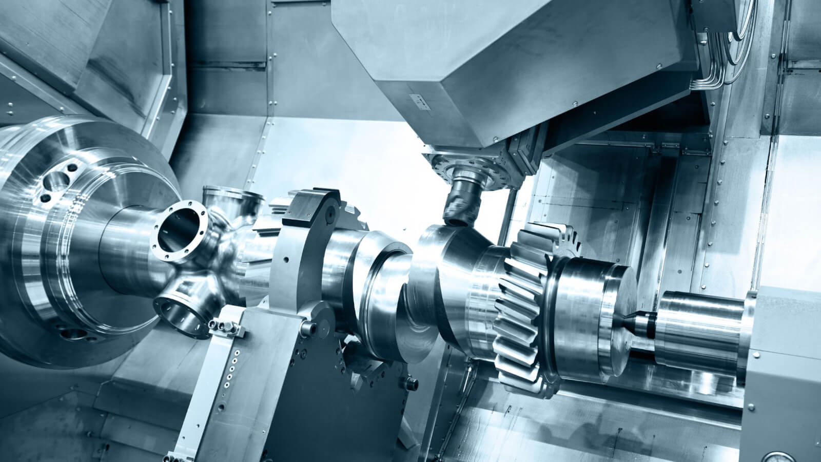
Introduction to Climb Milling Precision at Honyo Prototype
At Honyo Prototype, we leverage advanced CNC machining techniques to deliver exceptional component quality and efficiency, with climb milling representing a cornerstone of our high-precision manufacturing capabilities. Climb milling—where the cutter rotation direction aligns with the feed direction—minimizes tool deflection, reduces heat generation, and produces superior surface finishes compared to conventional milling. This method is particularly critical for complex geometries, thin-walled features, and high-tolerance applications common in aerospace, medical, and robotics prototyping. Our state-of-the-art CNC mills, paired with expert process engineering, ensure optimal toolpath strategies that maximize material removal rates while maintaining micron-level accuracy across aluminum, titanium, plastics, and exotic alloys.
Honyo’s commitment to precision extends beyond machining: our integrated workflow includes rigorous material certification, in-process inspections, and post-machining validation to guarantee dimensional integrity. For engineers requiring rapid iteration, our Online Instant Quote system accelerates project initiation—simply upload CAD files to receive detailed pricing, lead times, and manufacturability feedback within minutes, eliminating traditional quoting delays without compromising technical rigor.
Climb Milling vs. Conventional Milling: Key Performance Factors
| Parameter | Climb Milling | Conventional Milling |
|---|---|---|
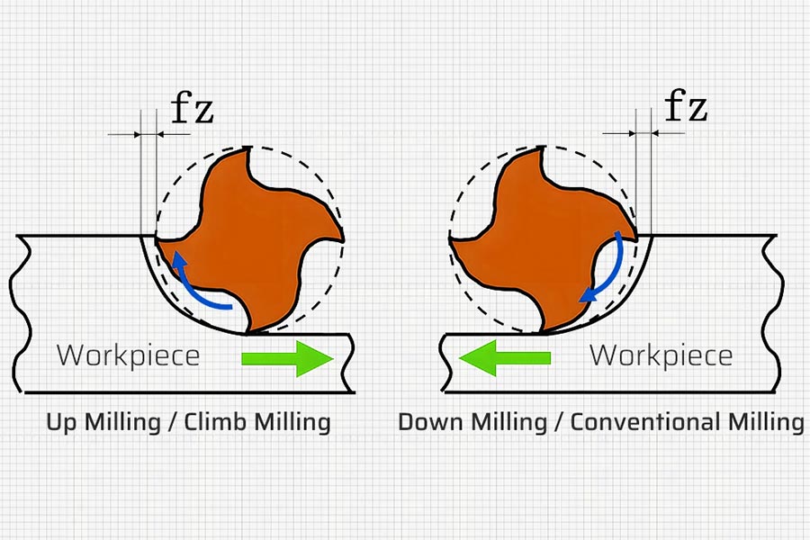
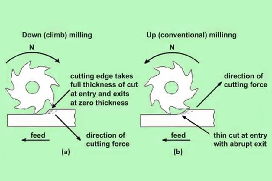
| Chip Thickness | Starts thick, decreases to zero | Starts thin, increases to maximum |
| Tool Deflection | Minimized (force pushes into workpiece) | Higher risk (force lifts workpiece) |
| Surface Finish | Superior (reduced rubbing/burrs) | Rougher (increased heat/work hardening) |
| Tool Wear | Even wear on cutting edge | Accelerated flank wear |
| Machine Requirement | Requires rigid setup, no backlash | Tolerates minor machine play |
Honyo Prototype engineers optimize climb milling protocols for your specific part requirements, ensuring cost-effective production without sacrificing quality. Initiate your next precision project with confidence—utilize our Online Instant Quote platform to transform CAD designs into actionable manufacturing plans immediately.
Technical Capabilities
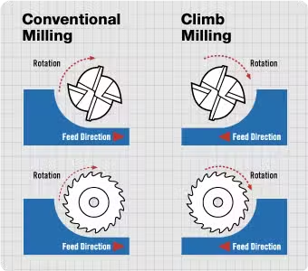
Climb machining, also known as down milling, is a milling technique where the rotation of the cutter is in the same direction as the feed of the workpiece. This method provides superior surface finish, reduced tool wear, and improved dimensional accuracy due to minimal work hardening and consistent chip thinning at the point of entry. It is particularly effective in high-precision 3-axis, 4-axis, and 5-axis milling operations, as well as in turn-mill combinations where tight tolerances (±0.0002″ to ±0.001″) are required.
Climb milling is preferred in modern CNC environments due to advanced machine rigidity and backlash compensation, ensuring optimal tool engagement and repeatability. It is widely used across aluminum, steel, ABS, and nylon materials, each requiring specific spindle speeds, feed rates, and tooling strategies to maintain tolerance and surface quality.
Below are the technical specifications and recommended parameters for climb machining across different materials and machining platforms:
| Parameter | 3-Axis Milling | 4-Axis Milling | 5-Axis Milling | Turning (Turn-Mill) |
|---|---|---|---|---|
| Spindle Speed (RPM) | 8,000–12,000 (Al), 6,000–8,000 (Steel), 10,000–15,000 (ABS/Nylon) | 7,000–10,000 (Al), 5,000–7,000 (Steel), 9,000–12,000 (ABS/Nylon) | 6,000–9,000 (Al), 4,000–6,000 (Steel), 8,000–10,000 (ABS/Nylon) | 1,500–3,000 (Al), 800–1,500 (Steel), 2,000–3,500 (ABS/Nylon) |
| Feed Rate (IPM) | 150–300 (Al), 80–150 (Steel), 200–400 (ABS/Nylon) | 120–250 (Al), 70–120 (Steel), 180–350 (ABS/Nylon) | 100–200 (Al), 60–100 (Steel), 150–300 (ABS/Nylon) | 0.005–0.015 ipr (Al), 0.003–0.008 ipr (Steel), 0.010–0.020 ipr (ABS/Nylon) |
| Axial Depth of Cut (DOC) | 0.02–0.125″ (finishing), up to 0.5″ (roughing) | 0.02–0.100″ (finishing), up to 0.4″ (roughing) | 0.01–0.080″ (finishing), up to 0.3″ (roughing) | 0.010–0.100″ (OD/ID), 0.005–0.030″ (finishing) |
| Radial DOC (WOC) | 10–40% of tool diameter | 10–35% of tool diameter | 5–30% of tool diameter | N/A |
| Tolerance Capability | ±0.0005″ typical, ±0.0002″ with high-end setup | ±0.0005″, ±0.0003″ with probing and thermal control | ±0.0003″, down to ±0.0001″ with in-process inspection | ±0.0005″ (diameter), ±0.001″ (length) |
| Surface Finish (Ra) | 16–32 μin (standard), 8–16 μin (polished) | 16–32 μin, 8–16 μin with fine tools | 16–32 μin, 8–12 μin with ball end or form tools | 16–63 μin (turning), 8–32 μin (hard turning or skimming) |
| Preferred Tooling | Carbide end mills (Al, Steel), solid carbide or diamond-coated (ABS/Nylon) | Same as 3-axis, with rotary axis compatibility | High-precision ball end mills, form tools, with tool length compensation | CBN or carbide inserts (Steel), AlTiN-coated (Al), uncoated for plastics |
| Coolant/Lubrication | Through-spindle coolant (Steel, Al), air blast or mist (ABS, Nylon) | High-pressure coolant for deep cavities, mist for non-metals | Minimal quantity lubrication (MQL) for precision, coolant for heavy cuts | Flood coolant (Steel), air or MQL (Al, plastics) |
| Materials Compatibility | Aluminum (excellent), Steel (good), ABS (good with sharp tools), Nylon (moderate, requires chip control) | Same as 3-axis, enhanced for complex geometries | Ideal for complex, tight-tolerance parts in all listed materials | Aluminum (high speed), Steel (controlled feed), ABS/Nylon (low heat buildup) |
Climb machining excels in applications demanding tight tolerances and high repeatability, especially when integrated with modern CNC controls, tool monitoring systems, and thermal compensation. Material behavior varies: aluminum responds well to high-speed climb cuts, steel requires robust tooling and cooling, while ABS and nylon benefit from sharp, polished tools and minimized heat input to prevent deformation.
From CAD to Part: The Process
Honyo Prototype utilizes the term Climb Machining to describe our integrated, client-centric workflow for rapid CNC machining and sheet metal fabrication projects. This is not a reference to the CNC milling technique climb milling but rather our proprietary end-to-end process designed to systematically overcome common prototyping and low-volume production hurdles. The process ensures technical rigor, cost efficiency, and accelerated time-to-part through the following sequential stages:
Upload CAD
Clients initiate the process by uploading native or neutral format CAD files (STEP, IGES, Parasolid, DWG/DXF) via our secure online portal. Our system performs an initial automated validation check for file integrity, unit consistency, and basic manufacturability flags. This stage captures critical metadata including material specifications, quantity, surface finish requirements, and geometric dimensioning and tolerancing (GD&T) callouts. The portal provides real-time confirmation of successful upload and initiates the quoting pipeline.
AI Quote
Honyo’s proprietary AI engine processes the validated CAD geometry alongside client-submitted requirements. The algorithm analyzes feature complexity, tool access constraints, material utilization, and machine time estimates based on our validated production database. Within 30 seconds, clients receive a detailed digital quote including:
Itemized cost breakdown (material, machining, finishing, overhead)
Predicted lead time with critical path analysis
Preliminary feasibility assessment highlighting potential high-risk features
Alternative material or process suggestions for cost optimization
This AI-driven stage eliminates manual quoting delays while maintaining engineering accuracy through continuous learning from historical production data.
DFM
Upon quote acceptance, our engineering team conducts a formal Design for Manufacturability review. This human-AI collaborative stage involves:
Verification of AI-identified risks through multi-axis simulation software
Tolerance stack analysis for critical interfaces
Material suitability assessment against functional requirements
Optimization of part orientation and workholding strategy
Generation of specific, actionable redesign recommendations where necessary (e.g., minimum wall thickness adjustments, fillet radius suggestions)
Clients receive a formal DFM report within 4 business hours, including annotated 3D models and revised cost/lead time projections reflecting any implemented design improvements. Client approval of the DFM package is required before production release.
Production
Approved designs enter our synchronized manufacturing environment:
Material procurement from certified suppliers with full material traceability
CAM programming using hyperMILL and Mastercam with G-code simulation validation
Machining on Haas and DMG MORI 3-5 axis centers with in-process probing
Real-time production monitoring via MTConnect-enabled equipment
First-article inspection using Zeiss CMMs against AS9102 format
All critical dimensions undergo statistical process control (SPC) tracking. Production status updates with timestamped milestone completion are accessible through the client portal.
Delivery
Final quality validation triggers our logistics protocol:
Full First Article Inspection Report (FAIR) generation
Dimensional conformance certification to ISO 17025 standards
Packaging meeting ESD and transit damage prevention specifications
Global shipping coordination with DHL/FedEx including real-time tracking
Post-delivery client satisfaction survey and technical debrief
The following table summarizes key performance metrics for the Climb Machining process:
| Process Stage | Typical Duration | Key Output | Quality Gate |
|---|---|---|---|
| Upload CAD | < 5 minutes | Validated geometry package | File integrity check |
| AI Quote | < 30 seconds | Binding price/lead time | Feasibility score ≥85% |
| DFM | ≤ 4 business hours | Approved manufacturing package | Client sign-off |
| Production | 3-15 business days* | FAIR-certified parts | Cpk ≥1.33 for critical features |
| Delivery | 1-3 business days | Trackable shipment | On-time delivery rate 98.7% |
*Duration varies based on complexity and quantity; 90% of standard prototypes ship within 5 business days. All stages include automated client notifications at milestone completion. This closed-loop system reduces client engineering hours by 60% compared to traditional quoting workflows while maintaining first-pass yield rates above 95%. Technical inquiries regarding specific material capabilities or tolerance capabilities should be directed to our applications engineering team.
Start Your Project
Interested in precision climb machining services? Contact Susan Leo today at [email protected] to discuss your project requirements. Our advanced manufacturing facility in Shenzhen ensures high-quality, efficient production tailored to your specifications.
🚀 Rapid Prototyping Estimator
Estimate rough cost index based on volume.