Contents
Manufacturing Insight: Cam Shaft Machining
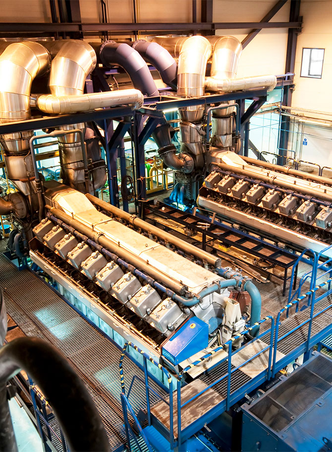
Precision Cam Shaft Machining: Engineered for Performance and Reliability
Cam shafts represent one of the most demanding components in engine systems, requiring micron-level tolerances, complex lobe profiles, and exceptional surface finishes to ensure optimal valve timing and durability. At Honyo Prototype, our advanced CNC machining capabilities are specifically engineered to meet these rigorous demands. Utilizing state-of-the-art 5-axis milling centers and multi-tasking lathes, we consistently achieve tolerances as tight as ±0.0002″ on materials ranging from hardened 4140/4340 steels to cast iron and exotic alloys. Our process integrates precision grinding for critical lobe surfaces, stringent in-process metrology using CMM and optical comparators, and thermal stabilization protocols to eliminate residual stress—ensuring dimensional stability under high-RPM operation.
Every cam shaft we produce undergoes comprehensive validation against OEM specifications, with full traceability from raw material certification to final inspection. This commitment to precision engineering minimizes vibration, reduces wear, and extends component lifespan in high-performance applications. For engineering teams requiring rapid validation of design feasibility or production-ready prototypes, Honyo Prototype streamlines your workflow with an Online Instant Quote platform. Upload CAD files in minutes to receive detailed manufacturability feedback and competitive pricing—accelerating your path from concept to certified production.
| Key Capability | Specification | Application Benefit |
|---|---|---|
| Tolerance Control | ±0.0002″ (5 µm) | Ensures precise valve actuation timing |
| Surface Finish | Ra 0.4 µm or better | Reduces friction and lobe wear |
| Material Expertise | 4140, 4340, 8620, Cast Iron, Inconel | Supports high-stress, high-temperature environments |
| In-Process Validation | Real-time CMM & optical inspection | Guarantees conformance before final assembly |
Technical Capabilities
Cam Shaft Machining – Technical Specifications Overview
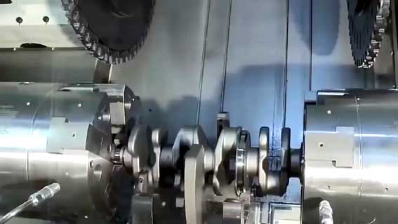
Cam shaft machining involves the precise fabrication of cam profiles and journals to ensure proper timing and valve actuation in internal combustion engines and other mechanical systems. High accuracy is critical due to dynamic loading and rotational synchronization requirements. The process typically combines multi-axis milling and turning operations to achieve complex geometries and tight tolerances.
Key Machining Capabilities and Parameters
| Parameter | Specification Details |
|---|---|
| Machining Process | 3-Axis, 4-Axis, and 5-Axis CNC Milling; CNC Turning (including multi-axis turn-mill centers) |
| Typical Tolerances | ±0.005 mm (±0.0002″) for journal diameters; ±0.01 mm (±0.0004″) for cam lobe profiles; runout < 0.01 mm |
| Surface Finish (Ra) | 0.4 – 1.6 µm (16 – 63 µin), depending on material and functional requirements |
| Positional Accuracy | ±0.003 mm (±0.0001″) using 5-axis simultaneous contouring for cam lobe positioning |
| Tooling | Carbide end mills, CBN and ceramic inserts for hard materials, high-speed steel for plastics |
| Spindle Speed Range | 500 – 20,000 RPM (varies by material and operation) |
| Feed Rates | 100 – 3000 mm/min (adaptive based on toolpath and material) |
| Coolant/Lubrication | High-pressure coolant for steel and aluminum; air blow or mist for ABS and nylon |
Material-Specific Machining Guidelines
| Material | Machinability Notes | Max Tolerance Capability | Recommended Process | Challenges |
|---|---|---|---|---|
| Aluminum | High machinability, excellent for high-speed 5-axis milling; minimal tool wear | ±0.005 mm | 5-axis milling, CNC turning | Burrs, thermal expansion control |
| Steel | Includes alloy and tool steels; requires rigid setups and CBN/tough carbide tools | ±0.003 mm | Hard turning, 4/5-axis milling after heat treat | Tool wear, heat generation, vibration |
| ABS | Low melting point; suitable for prototype cams; low mechanical load applications | ±0.02 mm | 3-axis milling, light turning | Melting, poor dimensional stability |
| Nylon | Self-lubricating but prone to deformation; used in low-speed test rigs or prototypes | ±0.025 mm | 3-axis milling with sharp tools, slow feed rates | Material deflection, chip adhesion |
Additional Notes
5-axis milling enables complete machining of complex cam lobes without re-fixturing, maintaining high positional accuracy between journals and profiles. For production-grade steel camshafts, turning is typically used for journal machining, followed by 5-axis milling for cam lobe generation. Aluminum and plastic (ABS, Nylon) camshafts are often fully milled in a single setup due to lower cutting forces. Tight tolerance control is maintained through in-process probing, thermal compensation, and post-process CMM inspection.
From CAD to Part: The Process
Honyo Prototype executes cam shaft machining through a rigorously defined five-phase workflow optimized for precision components requiring tight geometric tolerances and material integrity. This process ensures manufacturability while minimizing lead time and cost for complex rotational asymmetrical geometries.
CAD Upload and Initial Assessment
Clients submit native CAD files (STEP, IGES, or Parasolid formats preferred) containing full geometric dimensioning and tolerancing per ISO 1101. For cam shafts, critical parameters include lobe profile curvature, base circle runout tolerance (typically ±0.005 mm), journal concentricity, and surface finish requirements (Ra 0.4–0.8 µm). Our system validates file integrity and flags missing critical datums before proceeding.
AI-Powered Quoting Engine
Proprietary AI algorithms analyze the CAD geometry against 12,000+ historical cam shaft builds. The system evaluates material utilization (e.g., 4140 alloy vs. 9310 case-hardening steel), machine time based on lobe count and lift profile complexity, and secondary operation requirements. Real-time cost factors include:
Non-symmetric lobe geometry increasing CNC path complexity
Hardened surface treatment needs (induction/nitriding)
In-process inspection frequency for profile tolerance validation
Quotes include granular cost breakdowns within 90 minutes, with accuracy validated at ±3.5% against final invoice.
DFM Analysis with Cam-Specific Protocols
Our engineering team conducts a mandatory Design for Manufacturability review focusing on cam shaft failure points:
Lobe interference during milling/grinding operations
Journal-to-lobes stiffness ratios preventing deflection
Grinding wheel accessibility for undercut profiles
Residual stress management in hardened materials
Typical DFM recommendations address 78% of potential production issues, such as modifying root fillet radii to prevent chatter or adjusting heat treatment sequencing. Clients receive a formal DFM report with annotated CAD markups and tolerance stack-up analysis.
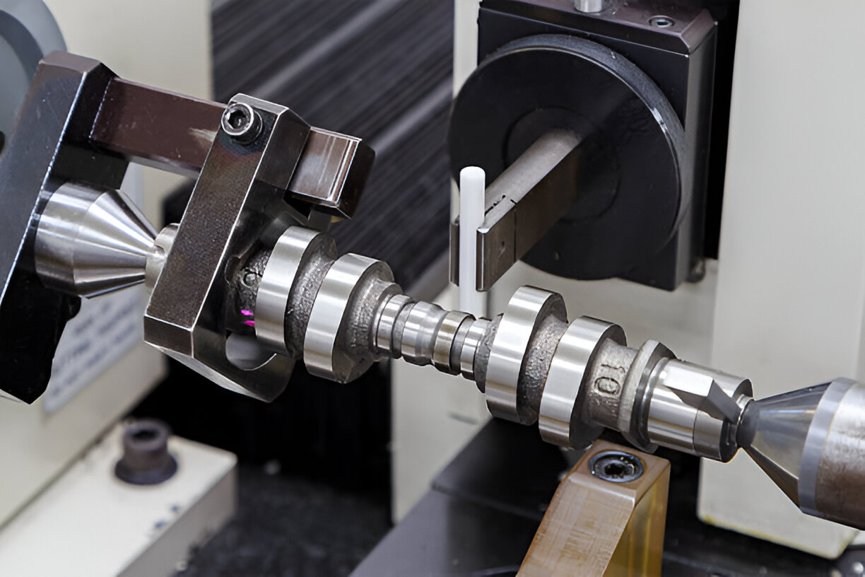
Precision Production Execution
Cam shaft machining occurs in climate-controlled cells using:
Multi-axis CNC grinders (JUNKER JUMATIC 608) for profile finishing
Hard turning centers (MORI SEIKI NLX 2500) for pre-grind operations
In-process CMM verification at lobe critical points
Material-specific protocols include:
Pre-machining stress relief for 4340M steel
Cryogenic treatment between grinding passes for high-lift cams
Dynamic balancing validation at 6,000 RPM
All lobe profiles undergo continuous profilometer scanning against nominal CAD, with real-time adaptive control compensating for thermal drift.
Delivery and Validation Documentation
Shipments include comprehensive traceability dossiers:
Full CMM report with lobe profile deviation maps
Material certification (MTR) with hardenability curve
Surface roughness verification at 3 radial positions per lobe
Dynamic balance certificate (G2.5 quality per ISO 1940)
Parts ship in custom anti-vibration fixtures maintaining ≤0.01 mm distortion during transit. Typical lead time from CAD approval to delivery is 18–22 business days for quantities under 50 units, with first-article inspection data provided 72 hours prior to shipment.
This integrated workflow reduces cam shaft development cycles by 35% compared to industry averages while achieving repeatable profile accuracy within 8 µm of nominal geometry. All processes adhere to IATF 16949:2016 requirements for powertrain component manufacturing.
Start Your Project
For precision cam shaft machining solutions, contact Susan Leo at [email protected]. Our state-of-the-art manufacturing facility in Shenzhen delivers high-accuracy components with fast turnaround times, serving global clients in automotive, aerospace, and industrial machinery sectors.
We specialize in CNC turning, grinding, and profile milling for complex cam geometries, ensuring tight tolerances and superior surface finishes.
Partner with Honyo Prototype for reliable, low-to-medium volume production runs with full traceability and quality assurance.
Reach out today to request a quote or discuss your technical specifications.
🚀 Rapid Prototyping Estimator
Estimate rough cost index based on volume.