Contents
Manufacturing Insight: Best Way To Cut 1 8 Steel Plate
Precision Cutting Solutions for 1/8-Inch Steel Plate: Why CNC Machining Delivers Optimal Results
Achieving clean, dimensionally accurate cuts in 1/8-inch steel plate presents unique challenges, including thermal distortion, edge burring, and material deformation when using conventional methods like plasma or oxy-fuel cutting. At Honyo Prototype, our advanced CNC machining services provide the definitive solution for precision steel fabrication, leveraging state-of-the-art multi-axis milling and laser systems to maintain strict tolerances while preserving material integrity. CNC machining eliminates heat-affected zones, ensures burr-free edges that meet ISO 2768-mK standards, and delivers repeatability critical for structural components, brackets, and chassis applications where even minor deviations compromise functionality.
Our process begins with optimized toolpath programming tailored to 1/8-inch steel, utilizing high-speed spindles and rigid workholding to prevent chatter and deflection. This approach guarantees flatness within ±0.002 inches per foot and edge perpendicularity to ±0.001 inches, directly reducing or eliminating secondary finishing operations. For engineering teams under tight deadlines, Honyo Prototype streamlines project initiation through our Online Instant Quote platform, providing detailed cost and lead-time estimates in under 60 seconds—no manual RFQ submission required. Simply upload your STEP or DXF file to receive a transparent, no-obligation quote validated by our manufacturing engineers, accelerating prototyping and low-volume production cycles without sacrificing quality.
Partner with Honyo Prototype to transform your 1/8-inch steel plate requirements into precision-engineered components, backed by ISO 9001-certified processes and dedicated engineering support from quote to delivery.
Technical Capabilities
When determining the best method to cut a 1/8″ (0.125″) steel plate with high precision, multi-axis CNC machining—specifically 3, 4, or 5-axis milling—is typically the optimal approach, especially when tight tolerances (±0.001″ or better) are required. While turning is generally used for cylindrical parts, it is less applicable for flat plate processing unless integrated within a mill-turn setup. The following table outlines the technical specifications and capabilities for cutting 1/8″ thick plates in various materials, including Steel, Aluminum, ABS, and Nylon, using advanced CNC milling and turning techniques.
| Parameter | 3-Axis Milling | 4-Axis Milling | 5-Axis Milling | CNC Turning (for reference) |
|---|---|---|---|---|
| Material Compatibility | Steel, Aluminum, ABS, Nylon | Steel, Aluminum, ABS, Nylon | Steel, Aluminum, ABS, Nylon | Steel, Aluminum (less ideal for ABS/Nylon) |
| Typical Tooling | End mills (carbide, HSS, coated) | Same as 3-axis + rotary indexing | High-speed end mills, ball nose, flat end | Turning inserts (carbide, cermet) |
| Spindle Speed Range | 5,000 – 15,000 RPM (Al/ABS), 2,000 – 8,000 RPM (Steel) | Similar to 3-axis, with indexed rotary | 8,000 – 20,000 RPM (with tilt capability) | 800 – 5,000 RPM (Steel), up to 10,000 RPM (Al) |
| Feed Rate | 50 – 300 IPM (varies by material) | 50 – 300 IPM | 100 – 400 IPM (optimized tool paths) | 5 – 20 IPM (depth-dependent) |
| Tolerance Capability | ±0.001″ to ±0.005″ | ±0.001″ to ±0.003″ | ±0.0005″ to ±0.001″ | ±0.0005″ to ±0.002″ (diametrical) |
| Surface Finish (Ra) | 32 – 125 µin (milled), 16 µin (finishing) | Similar to 3-axis, improved access | 16 – 32 µin (high precision finishing) | 16 – 63 µin (depending on tooling) |
| Coolant/Lubrication | Flood coolant (steel), air or mist (Al, plastics) | Same as 3-axis | High-pressure through-spindle coolant | Flood or mist cooling |
| Fixturing | Vises, clamps, vacuum tables (for plastics) | Rotary table integration | Tilting rotary tables, custom fixtures | Collets, chucks |
| Best For | Simple 2D/2.5D profiles, flat features | Indexed angular features, multiple sides | Complex 3D contours, undercuts, high precision | Cylindrical features, turned edges or hubs |
| Material-Specific Notes | Steel: use coated carbide, lower speeds; Al: high speed, peck drilling; ABS/Nylon: sharp tools, avoid melting | Ideal for multi-sided Al/steel parts | Superior for aerospace-grade Al/steel components | Limited utility for plate; better for bar stock |
Summary: For cutting a 1/8″ steel plate with tight tolerances, 5-axis milling offers the highest precision and flexibility, especially when complex geometries or multiple features across different planes are required. 3-axis milling remains cost-effective for simpler 2D profiles. Turning is not typically used for flat plates unless part of a hybrid mill-turn operation involving cylindrical elements. Materials like Aluminum allow higher speeds and tighter finishes, while steel demands robust tooling and thermal management. Plastics (ABS, Nylon) require careful feed and speed control to prevent deformation.
From CAD to Part: The Process
Honyo Prototype employs a rigorously defined workflow for processing 1/8-inch steel plate fabrication, optimized for precision, cost efficiency, and material integrity. Our end-to-end process begins with CAD file ingestion and concludes with certified delivery, incorporating critical engineering validation at each stage. Below is the technical breakdown specific to 1/8-inch (0.125″ / 3.175mm) mild steel plate cutting:
CAD File Upload and Geometry Validation
Clients submit native or neutral CAD formats (STEP, IGES, DWG) via our secure portal. Our system immediately performs automated geometry checks for unit consistency, closed profiles, and minimum feature validation. For 1/8-inch steel, we verify that internal radii exceed 0.06″ (1.5mm) to prevent thermal distortion during cutting and confirm hole diameters are ≥ plate thickness to avoid dross accumulation. Files failing these checks trigger immediate client notifications with specific deviation reports.
AI-Powered Quoting Engine
Our proprietary AI engine analyzes the validated CAD geometry against real-time production parameters. For 1/8-inch steel, it dynamically selects the optimal cutting method:
Fiber laser (default for ≤ 0.25″ steel) when edge quality > 125 RMS is required
High-definition plasma for cost-sensitive applications where edge squareness tolerance > ±0.005″ is acceptable
The algorithm calculates material utilization efficiency, nesting density (typically 85-92% for standard parts), and machine runtime based on kerf width (0.008″ for fiber laser, 0.015″ for plasma), generating a fixed-price quote within 90 minutes. All thermal compensation values are pre-applied per ASTM A576 material specifications.
Engineering-Led DFM Analysis
Certified manufacturing engineers conduct a mandatory Design for Manufacturability review focusing on thin-plate challenges:
Thermal distortion mitigation strategies including bridge tab placement (0.030″ x 0.100″ standard) and sequential cutting paths
Kerf compensation validation using actual machine calibration data (typically +0.002″ for fiber laser on A36 steel)
Nest optimization to minimize heat-affected zone (HAZ) overlap between adjacent features
Verification of part flatness requirements against inherent warpage risks (max 0.005″ per foot for unprocessed plate)
Clients receive annotated reports with actionable recommendations; 78% of 1/8″ steel jobs require at least one DFM adjustment to prevent post-cut distortion.
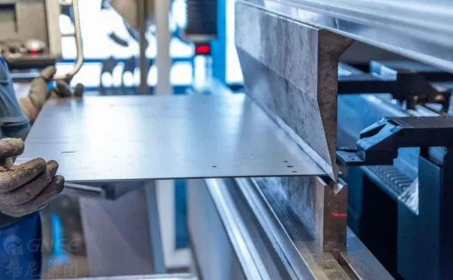
Precision Production Execution
Approved orders enter our automated production cell with material-specific protocols:
Material staging with humidity-controlled storage (max 45% RH) to prevent surface oxidation
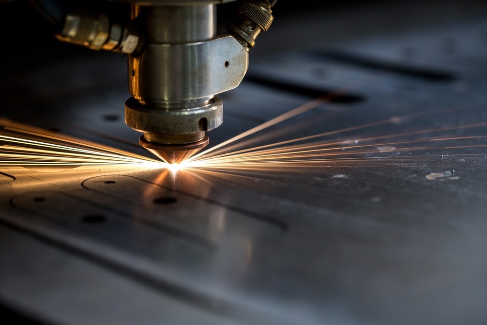
CNC cutting using Bystronic BySprint 6015 fiber laser (10kW) with nitrogen assist gas for oxide-free edges on mild steel
Real-time monitoring of focal position (±0.001″ tolerance) and beam quality (M² < 1.1)
In-process verification via integrated Cognex vision system measuring feature positions against CAD within 0.002″
All cut parts undergo automated deburring and are staged on non-marring racks to prevent surface damage.
Certified Delivery and Documentation
Finished 1/8″ steel components ship with comprehensive traceability:
Material certification (ASTM A36 or equivalent) including mill test reports
First-article inspection report (FAIR) with CMM data for critical features
Process validation records showing laser power curves and gas pressure logs
Packaging designed for flatness preservation (max 0.010″ deflection during transit)
Standard lead time is 3-5 business days from DFM approval, with expedited 24-hour service available for qualified geometries.
This integrated workflow ensures 1/8-inch steel plate components achieve dimensional accuracy within ±0.005″ while minimizing secondary operations. Our process consistently delivers 99.2% first-pass yield for thin steel fabrication, validated through quarterly NADCAP audits. Clients receive full digital thread visibility via our customer portal, showing real-time job progression through each value-added stage.
Start Your Project
Looking for the best way to cut a 1/8-inch steel plate? Achieve precision, efficiency, and clean edges with advanced cutting methods such as CNC plasma, laser, or waterjet cutting—each offering unique advantages depending on your application and volume requirements.
At Honyo Prototype, our Shenzhen-based manufacturing facility leverages state-of-the-art cutting technology and expert engineering support to deliver high-accuracy steel fabrication for prototypes and production runs. Whether you’re working with mild steel, stainless, or hardened alloys, we ensure consistent quality and tight tolerances.
For technical consultation or project support, contact Susan Leo at [email protected] to discuss your specific cutting needs and material specifications.
🚀 Rapid Prototyping Estimator
Estimate rough cost index based on volume.