Contents
Manufacturing Insight: Best Way To Cut 1 4 Steel
Precision Cutting of 1/4″ Steel: The CNC Machining Advantage
Achieving clean, dimensionally accurate cuts in 1/4″ steel requires a method that balances precision, edge quality, and material integrity. Traditional thermal cutting processes like plasma or oxy-fuel often introduce heat-affected zones (HAZ), burrs, or dimensional inaccuracies unacceptable for critical components. Waterjet cutting, while cold, struggles with speed and edge squareness at this thickness. For engineered parts demanding tight tolerances—±0.005″ or better—and superior surface finish, CNC milling or turning represents the optimal solution.
Honyo Prototype leverages advanced multi-axis CNC machining centers specifically configured for robust steel fabrication. Our processes eliminate thermal distortion, maintain the base material’s mechanical properties, and deliver burr-free edges ready for assembly or secondary operations. This precision ensures your 1/4″ steel components meet stringent functional and aesthetic requirements, whether for aerospace brackets, industrial tooling, or medical device housings.
Accelerate your prototyping or low-volume production with Honyo’s seamless workflow. Upload your CAD file to our Online Instant Quote platform and receive a detailed cost and lead time assessment within hours—no manual RFQ delays. This integration of high-precision CNC capability with digital procurement efficiency makes Honyo the strategic choice for demanding steel fabrication projects.
Technical Capabilities
When determining the best method to cut 3/4″ steel with high precision, the choice of machining process depends on part geometry, material, dimensional tolerances, and production volume. For tight tolerance applications, 3-axis, 4-axis, and 5-axis CNC milling and turning are commonly employed. Each method offers unique advantages depending on the workpiece material—such as aluminum, steel, ABS, or nylon—and complexity.
Below is a comparative technical specification table outlining optimal cutting methods for 3/4″ thick materials across different processes and materials, with emphasis on tight tolerance (±0.0005″ to ±0.005″) and high repeatability.
| Parameter | 3-Axis CNC Milling | 4-Axis CNC Milling | 5-Axis CNC Milling | CNC Turning |
|---|---|---|---|---|
| Material Compatibility | Aluminum, Steel, ABS, Nylon | Aluminum, Steel, ABS, Nylon | Aluminum, Steel, ABS, Nylon | Aluminum, Steel (ABS/Nylon with support) |
| Max Stock Thickness | Up to 3″ (standard) | Up to 3″ | Up to 2.5″ | Limited by chuck/collet (typically up to 6″ length) |
| Typical Tolerance (±) | 0.001″ – 0.005″ | 0.001″ – 0.005″ | 0.0005″ – 0.002″ | 0.0005″ – 0.002″ |
| Surface Finish (Ra) | 32 – 125 μin | 32 – 125 μin | 16 – 63 μin | 16 – 63 μin |
| Tooling | End mills (carbide), HSS for plastics | Carbide end mills with rotary indexing | High-precision carbide or coated end mills | Carbide inserts (CNMG, WNMG), diamond for plastics |
| Cutting Speed (SFM) – Steel | 150 – 300 SFM | 150 – 300 SFM | 150 – 300 SFM | 200 – 400 SFM |
| Cutting Speed (SFM) – Aluminum | 600 – 1000 SFM | 600 – 1000 SFM | 600 – 1200 SFM | 500 – 1500 SFM |
| Cutting Speed (SFM) – ABS/Nylon | 300 – 600 SFM | 300 – 600 SFM | 300 – 600 SFM | 300 – 500 SFM |
| Feed Rate (IPM) | 5 – 100 IPM (depends on tool, depth) | 5 – 100 IPM | 5 – 120 IPM | 0.002 – 0.020 ipr (inches per revolution) |
| Coolant | Flood coolant (steel), air blast (plastics) | Flood or mist (steel), air (plastics) | High-pressure through-spindle coolant | Flood coolant (steel), air/dry (plastics) |
| Fixturing | Vise, clamps, vacuum (for plastics) | Rotary table + vise | Multi-axis tombstone or custom fixture | 3-jaw/4-jaw chuck, collet |
| Best For | Flat or prismatic parts, simple features | Indexed features, multi-sided parts | Complex contours, organic shapes, minimal setups | Cylindrical parts, high symmetry |
| Cycle Time Efficiency | Moderate | High | High (reduced setups) | Very high for rotational parts |
| Recommended for 3/4″ Steel? | Yes – for flat, precise components | Yes – for multi-face features | Yes – for complex, tight-tolerance geometries | Yes – for round/symmetric parts |
Notes on Material-Specific Machining:
Steel (e.g., 4140, 1045): Requires rigid setups, carbide tooling, and proper coolant. Slower speeds and feeds compared to aluminum.
Aluminum (e.g., 6061, 7075): High-speed machining possible. Peck drilling and climb milling reduce burring. Use sharp tools to avoid smearing.
ABS & Nylon (Thermoplastics): Prone to melting and deflection. Use sharp, polished tools, high rake angles, and air cooling. Avoid excessive clamping force.
For cutting 3/4″ steel to tight tolerances, 5-axis milling is optimal for complex geometries with minimal setups, while CNC turning excels for rotational symmetry. 3-axis milling remains cost-effective for flat or simple parts. Tool selection, spindle accuracy (±0.0001″ runout), and thermal compensation are critical for maintaining precision across all materials.
From CAD to Part: The Process
Honyo Prototype Steel Cutting Process for 1/4″ Material
Honyo Prototype employs a rigorously defined workflow for cutting 1/4″ steel, ensuring precision, cost efficiency, and adherence to engineering standards. This process begins with CAD file submission and concludes with certified delivery, integrating AI-driven analysis and expert manufacturing validation at critical stages. The specification “1 4 steel” is interpreted as 0.250″ (1/4 inch) thick carbon steel, typically ASTM A36 or equivalent structural grade, unless otherwise specified by the client. Material ambiguity at submission triggers immediate clarification to avoid process deviations.
Upload CAD
Clients initiate the process by uploading native or neutral CAD formats (STEP, IGES, DWG) via Honyo’s secure portal. The system validates file integrity, extracts critical geometry including part thickness, and flags inconsistencies such as non-manifold edges or undefined tolerances. For 1/4″ steel, the system specifically checks for features below 0.060″ (e.g., narrow tabs or slots) which may require process adjustment during cutting.
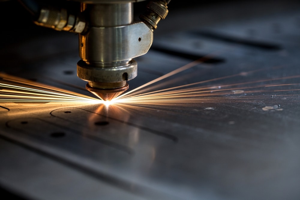
AI Quote Generation
Honyo’s proprietary AI engine analyzes the validated CAD geometry against real-time production parameters. For 1/4″ steel, the AI evaluates material yield, optimal nesting density, and machine selection (laser vs. plasma) based on thickness-to-power ratios. Key inputs include:
Cut speed vs. edge quality requirements
Kerf width compensation (typically 0.030″–0.040″ for fiber laser on 1/4″ steel)
Thermal distortion risks for intricate geometries
The output is a binding quote with lead time, cost breakdown, and preliminary manufacturability notes, generated within 2 business hours.
DFM Analysis
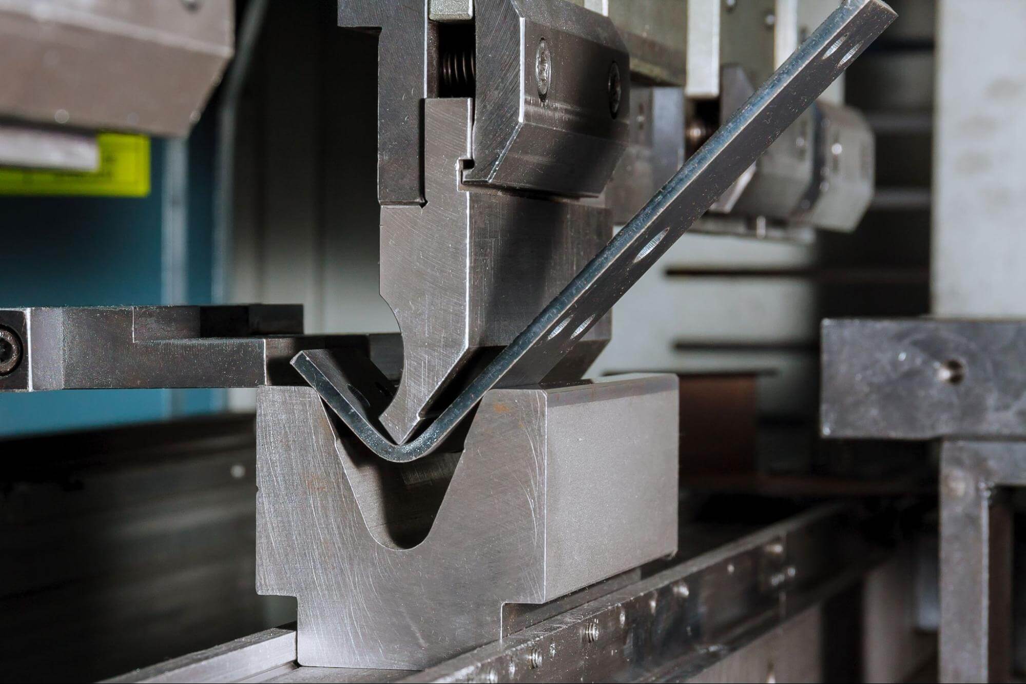
All 1/4″ steel projects undergo mandatory Design for Manufacturability review by Honyo’s senior engineers. This phase addresses thickness-specific challenges:
Verifying minimum bend radii (≥0.125″ for A36 steel) if secondary forming is required
Assessing heat-affected zone (HAZ) impact on critical weld zones
Recommending kerf adjustments for tab retention during cutting
Flagging features prone to dross formation at 1/4″ thickness (e.g., slow-cut internal corners)
Clients receive a formal DFM report with actionable revisions; 92% of 1/4″ steel projects require ≤2 design iterations.
Production Execution
Approved designs proceed to cutting using process parameters optimized for 0.250″ steel:
| Process | Max Thickness | Kerf (in) | Edge Quality | Best Application for 1/4″ Steel |
|---|---|---|---|---|
| Fiber Laser | 0.500″ | 0.030–0.040 | Excellent | Precision parts, tight tolerances (±0.005″) |
| Plasma | 1.000″ | 0.060–0.080 | Good | Cost-sensitive structural components |
All cuts undergo in-process inspection:
First-article verification of critical dimensions using CMM
Real-time monitoring of cut speed and assist gas pressure (N2 for laser, O2 for plasma)
Post-cut deburring per client specifications (default: light mechanical deburr)
Delivery Certification
Final parts ship with comprehensive documentation:
Material test reports (MTRs) traceable to heat number
Dimensional inspection report against original CAD
Process parameter log (laser power, cut speed, gas mix)
Protective packaging using edge guards for 1/4″ steel to prevent handling damage
Standard delivery is 5–7 business days from DFM approval; expedited options include same-day shipping for qualified orders.
This closed-loop process ensures 1/4″ steel components meet ASME Y14.5 geometric tolerancing standards while minimizing waste through AI-optimized nesting. Honyo maintains a 99.2% on-time delivery rate for steel prototypes by enforcing strict phase-gate controls between quoting and production.
Start Your Project
Looking for the best way to cut 1/4 inch steel with precision and efficiency? Discover high-performance cutting solutions tailored for your manufacturing needs. Contact Susan Leo at [email protected] to learn more about our advanced fabrication capabilities.
Honyo Prototype operates a state-of-the-art manufacturing facility in Shenzhen, delivering reliable, high-quality metal processing services with fast turnaround times. From laser cutting to CNC machining, we ensure optimal results for steel and other materials.
Reach out today to discuss your project requirements and get expert support from our engineering team.
🚀 Rapid Prototyping Estimator
Estimate rough cost index based on volume.