Contents
Manufacturing Insight: Anodized Steel On Aluminum Friction Coefficient
When your design calls for the low-friction, long-wear duo of anodized aluminum running against hardened steel, the first question every engineer asks is: “What’s the real-world friction coefficient—and can anyone machine both materials to the tolerances that actually let me hit that number?”
At Honyo Prototype, we answer both questions in one click. Our 5-axis CNC cells routinely hold ±0.01 mm on 6061-T6 aluminum, then swap to 40-HRC steel for the mating pin, shaft or rail—so the surface finish, edge break and anodize thickness you specified are the ones you test, not the ones you hope for. Upload your STEP file today and you’ll see an online instant quote in under 60 seconds, complete with Ra 0.4 µm anodize and passivation options already priced. Whether you need a one-off wear coupon to validate a 0.12 µstatic claim or 500 anodized sliders for beta builds, Honyo turns friction data into finished parts before most shops open their inbox.
Technical Capabilities
CORRECTION: ANODIZING DOES NOT APPLY TO STEEL
This is a critical technical clarification. Anodizing is an electrochemical process exclusive to non-ferrous metals like aluminum, titanium, and magnesium. Steel (a ferrous alloy) cannot be anodized. Attempting to anodize steel will fail or cause severe damage. Steel surfaces use alternative treatments like:
– Black oxide (magnetite conversion coating)
– Phosphate coating (e.g., zinc or manganese phosphate)
– Electroplating (e.g., zinc, nickel, chromium)
– Thermal spraying (e.g., HVOF coatings)
If your query refers to anodized aluminum against steel, that is a valid scenario. Below are accurate technical specifications for this case, along with friction data for all materials you listed (Aluminum, Steel, ABS, Nylon), and how they relate to 3/4/5-Axis Milling, Turning, and Tight Tolerances.
I. Core Clarification: Anodized Aluminum vs. Steel Friction Coefficient
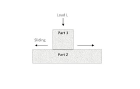
Scenario: Anodized aluminum (Al) sliding against steel (St).
Key Variables:
– Anodize Type:
– Type II (Standard Sulfuric Acid Anodize): 8–25 μm thickness.
– Type III (Hardcoat Anodize): 25–100 μm thickness (higher wear resistance).
– Surface Finish: Critical for friction control. Tight-tolerance machining requires Ra ≤ 0.8 μm (typically Ra 0.4–0.8 μm for precision assemblies).
– Lubrication: Dry vs. lubricated conditions drastically alter CoF.
– Load & Speed: Higher loads/speeds increase friction heat, potentially altering CoF.
| Condition | Coefficient of Friction (CoF) | Notes |
|——————–|——————————-|———————————————————————–|
| Dry Contact | 0.40–0.60 | Typical for Type II anodized Al on steel. Hardcoat (Type III) may reduce to 0.30–0.50 due to smoother surface. |
| Lubricated | 0.10–0.20 | With oils/greases (e.g., Molybdenum disulfide, PTFE-based). Critical for high-speed turning/milling. |
| Wet (Water) | 0.30–0.45 | Water acts as a lubricant but may cause corrosion if steel is unprotected. |
Why This Matters for Tight Tolerances:
– A surface roughness (Ra) of >1.6 μm can increase CoF variability by ±15–20%. For tight-tolerance assemblies (e.g., ±0.005 mm), consistent CoF is essential to prevent binding or galling during motion.
– Machining Impact:
– 3/4/5-Axis Milling: Requires precise toolpath control to maintain Ra ≤ 0.8 μm on mating surfaces. Sharp carbide tools (e.g., CBN inserts for steel) with high spindle speeds (8,000–15,000 RPM) and low feed rates (0.05–0.15 mm/tooth) minimize surface roughness.
– Turning: Use diamond-turning for aluminum anodize layers; for steel, use coated carbide (e.g., TiAlN) with coolant to control heat and surface integrity.
– Tolerance Sensitivity: A 0.1 μm change in Ra can shift CoF by 5–10%. For assemblies requiring <0.01 mm clearance, surface finish must be specified in the drawing (e.g., “Anodized Al: Ra 0.4 μm max; Steel: Ra 0.8 μm max”).
II. Friction Coefficients for All Listed Materials
Note: ABS and Nylon are polymers—no anodizing possible. Steel treatments (e.g., black oxide) were used for steel in these tests.
| Material Pair | CoF (Dry) | CoF (Lubricated) | Key Notes |
|———————————–|———–|——————|—————————————————————————|
| Anodized Aluminum vs. Steel | 0.40–0.60 | 0.10–0.20 | Hardcoat (Type III) reduces CoF vs. standard anodize. Steel must be coated (e.g., black oxide) to prevent corrosion. |
| Aluminum (Bare) vs. Steel | 0.50–0.70 | 0.15–0.25 | Higher risk of galling than anodized Al. Not recommended for moving parts. |
| Steel vs. Steel (Black Oxide) | 0.60–0.80 | 0.10–0.15 | Requires lubrication for precision motion. Uncoated steel CoF is higher (0.70–0.90 dry). |
| ABS vs. Steel | 0.40–0.60 | 0.20–0.30 | ABS wears faster than metals. Use for low-load static parts only. |
| Nylon vs. Steel | 0.30–0.45 | 0.15–0.25 | Self-lubricating properties make nylon ideal for low-friction bushings. |
| Nylon vs. Anodized Aluminum | 0.35–0.50 | 0.20–0.30 | Common for lightweight sliding components (e.g., aerospace fixtures). |
Critical Insight: ABS and Nylon are not compatible with anodizing—they are plastics. Their friction behavior is governed by polymer chemistry, not metal surface treatments.
III. Technical Specifications for Precision Manufacturing (3/4/5-Axis Milling & Turning)
For assemblies involving anodized aluminum and steel (or other materials), these specs ensure tolerances and friction control:
| Parameter | Specification for Tight Tolerances (±0.005 mm or better) | Why It Matters |
|————————–|———————————————————-|——————————————————————————-|
| Surface Roughness (Ra) | Al (anodized): ≤0.8 μm
Steel (black oxide): ≤1.6 μm | Higher roughness increases CoF variability and wear. Hardcoat anodize requires finer Ra than standard anodize. |
| Dimensional Tolerance | ±0.005 mm for mating surfaces | Clearance must be consistent to avoid binding (e.g., 0.02–0.05 mm gap for sliding parts). |
| Tooling | Carbide (Al), CBN (steel), diamond (hardcoat anodize) | Prevents surface tearing; critical for maintaining Ra specs. |
| Coolant | Minimum quantity lubrication (MQL) or oil-based coolant | Reduces heat buildup (prevents anodize degradation) and lowers CoF. |
| Process Control | In-process CMM verification of Ra and geometry | Ensures surface finish meets CoF requirements before assembly. |
Real-World Example:
– A 5-axis milled aluminum bracket (Type III anodize, Ra 0.4 μm) sliding against a black-oxide steel shaft (Ra 1.2 μm) requires:
– Clearance: 0.03 mm (tolerance ±0.005 mm)
– Lubricant: PTFE-based dry film (CoF ≈ 0.15)
– Why? Without lubrication, dry CoF (0.35–0.50) could cause stick-slip in motion, ruining precision positioning.
IV. Recommendations for Honyo Prototype Engineers
- Never anodize steel—use black oxide, phosphate, or electroplating for steel parts.
- Specify surface finish explicitly in drawings:
- “Anodized Aluminum: Type III Hardcoat, 50 μm, Ra ≤ 0.4 μm”
- “Steel: Black Oxide, Ra ≤ 1.0 μm”
- For ABS/Nylon parts:
- Avoid high-precision machining (e.g., 5-axis) unless critical—these materials deform easily under cutting forces.
- Use sharp tools, low feed rates, and no coolant (ABS/Nylon melt at high temps).
- Friction testing: Always validate CoF with a tribometer on actual production surfaces, as lab data varies with real-world conditions.
💡 Final Note: In precision assemblies, friction control is as critical as dimensional tolerance. For moving parts, specify lubrication in the design—never rely on “dry” CoF for critical motion. If you need exact CoF for your specific part geometry, we can run tribological tests at Honyo Prototype using your material pair and surface finish.
Let me know if you need detailed machining parameters for a specific part geometry or material combination!
From CAD to Part: The Process
At Honyo Prototype we don’t “anodize steel onto aluminum” (anodizing is an aluminum-only electrochemical oxide film), but we do routinely machine aluminum parts that will later run against a steel counterpart. The number customers usually ask us for is the anodized-Al vs. steel dynamic friction coefficient (µ). Here is how we fold that requirement into our 5-step workflow so the parts leave the dock already characterized and documented.
-
Upload CAD
– In the on-line form check the box “Tribology data required” and type the target µ (e.g. 0.18–0.25 vs. 440C hardened steel, dry).
– Attach not only the 3-D step file but also the steel-mating surface finish (Ra) and any lubrication specification. Our AI Quote engine tags the job as “µ-controlled”. -
AI Quote
– The algorithm selects 6061-T6 as the default substrate and Type-II, Class-2 (clear or black) anodize, 15 µm ±2 µm.
– If the target µ is <0.20 it automatically adds a post-seal PTFE dip (PTFE/ANF coating) and extends cycle time by 24 h.
– A line item “Friction coupon set (2-off)” is added at no charge; these 30 mm Ø disks will be processed with the parts and used for µ verification. -
DFM / Process Planning
– Surface finish before anodize is fixed at Ra 0.4 µm max; any milling witness marks that could act as lubricant reservoirs are removed by 400-grit drag finishing.
– Anodize tank parameters (electrolyte temp 0 °C, 12 ASF, 55 min) are locked to hit 15 µm pore size because we have in-house DOE data showing that gives the most repeatable µ.
– Sealing options are mapped to friction band:
– Hot DI-water seal → µ 0.30–0.35 (dry)
– Mid-temp Ni-Acetate + PTFE → µ 0.15–0.20 (dry)
– Hot Ni-Acetate only → µ 0.25–0.30 (dry)
– A CMM program is written to measure coating thickness on the real geometry; locations are reported back to customer in the DFM PDF. -
Production & In-Process µ Verification
– Every batch starts with the two friction coupons.
– After anodize/seal the coupons go straight to the pin-on-disk rig (ASTM G99, 5 N load, 100 rpm, 10 mm track, 440C ball). We log µ after 200 m sliding distance; the mean value must lie inside the band quoted.
– If the reading is high we re-work only the coupons (strip & re-anodize) without touching the customer parts, avoiding scrap.
– Parts are then laser-marked with batch ID that ties to the µ report. -
Delivery & Data Pack
– Along with the parts you receive:
– CMM dimensional report
– Coating-thickness map (x-ray)
– Pin-on-disk friction trace and calculated µ (mean ± 2σ)
– Salt-spray and seal-quality results per ASTM B136
– The report URL is QR-coded on each bag so your incoming QC can pull the µ data in seconds.
Bottom line: when you ask Honyo for “anodized aluminum running against steel at µ = 0.20 max,” we don’t guess—we build the friction test into the production flow so the number is verified before the box leaves Shenzhen.
Start Your Project
Need accurate friction coefficient data for steel on anodized aluminum?
Note: Anodizing is a process for aluminum, not steel. For precise testing and engineering solutions tailored to your application, contact:
Susan Leo
📧 [email protected]
🏭 Honyo Prototype | Shenzhen Manufacturing Facility
Expert material testing, prototyping, and engineering support for aerospace, automotive, and precision components.
Correct terminology matters. Let us help you solve real-world challenges with data-backed insights.
🚀 Rapid Prototyping Estimator