Contents
Manufacturing Insight: 3D Printing Interlocking Parts
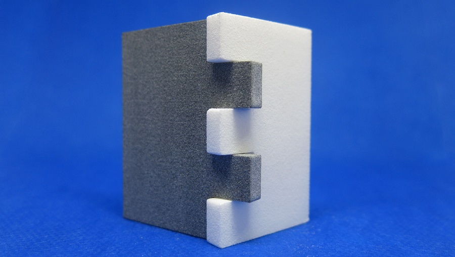
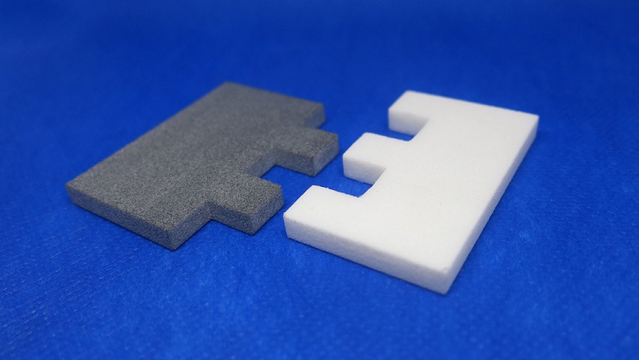
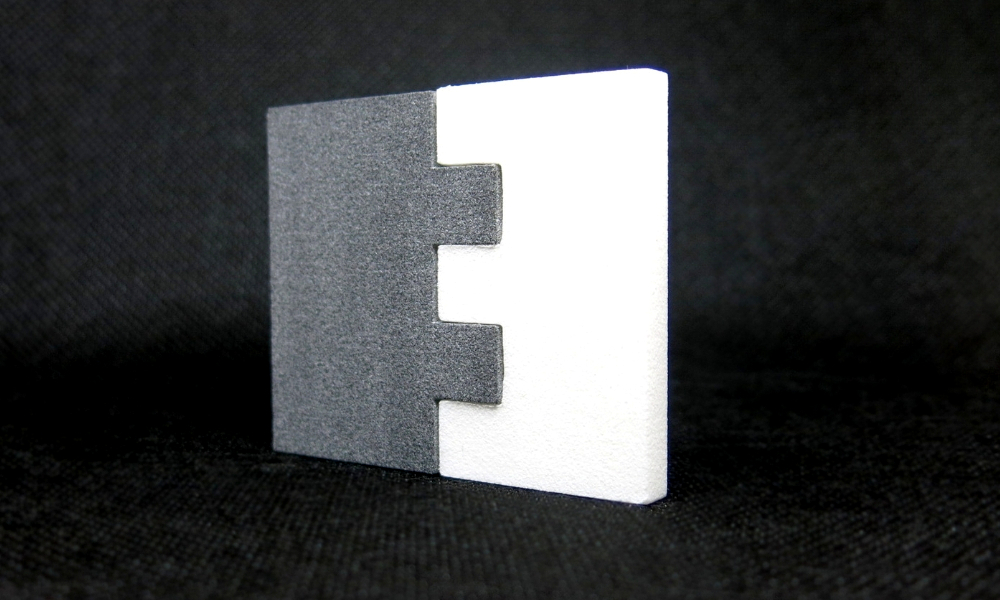
Precision Interlocking Assemblies: Engineered for Seamless Integration
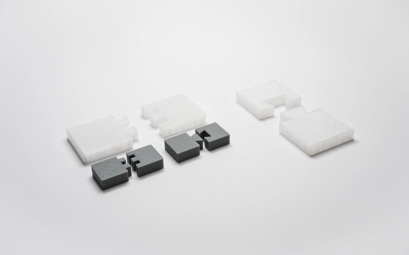
Traditional manufacturing of multi-part assemblies often introduces supply chain complexity, alignment errors, and costly secondary operations. Honyo Prototype eliminates these bottlenecks through advanced Industrial 3D Printing, specifically engineered for high-fidelity interlocking components. Our end-to-end solution leverages industrial-grade polymer and metal additive systems to produce integrated assemblies—such as snap-fits, living hinges, and nested couplings—with micron-level accuracy, eliminating post-assembly adjustments and reducing part count by up to 70%.
We deploy validated processes across SLS, MJF, and DMLS platforms, using engineering thermoplastics like PA12 GF and metals including AlSi10Mg, ensuring mechanical performance meets or exceeds injection-molded equivalents. Every interlocking design undergoes rigorous Design for Additive Manufacturing (DfAM) analysis to optimize wall thickness, clearance tolerances, and stress distribution, guaranteeing functional reliability in final-use applications.
Accelerate your path from concept to validation with Honyo’s Online Instant Quote platform. Upload your CAD file to receive a comprehensive technical and commercial assessment within minutes—including material options, lead time projections, and actionable DfAM feedback—enabling rapid iteration without engineering delays. This integration of industrial-scale capability and digital procurement streamlines complex assembly production for aerospace, medical devices, and industrial equipment sectors.
Technical Capabilities
The technical specifications for 3D printing interlocking parts vary significantly across SLA, SLS, MJF, and DMLS processes due to differences in resolution, material properties, and design tolerances. Below is a comparison of key parameters for each technology, including compatible materials such as Aluminum, Steel, ABS-like, and Nylon, with emphasis on achieving functional interlocking geometries.
| Process | Technology Overview | Typical Layer Thickness | Minimum Feature Size | Recommended Clearance for Interlocking Parts | Common Materials | Material Properties Relevant to Interlocking Parts | Post-Processing Requirements |
|---|---|---|---|---|---|---|---|
| SLA (Stereolithography) | Photopolymerization using UV laser on liquid resin | 25–100 µm | 150–300 µm | 0.2–0.5 mm (tight fit), 0.6–1.0 mm (loose fit) | Photopolymers (ABS-like, rigid, flexible resins) | High surface finish; low wear resistance; prone to brittleness over time; suitable for prototypes | Support removal, IPA wash, UV curing; may require coating for durability |
| SLS (Selective Laser Sintering) | Laser fuses powdered Nylon; no supports needed | 80–120 µm | 0.5–1.0 mm | 0.3–0.6 mm (standard), 0.2 mm achievable with calibration | Nylon 12 (PA12), Glass-filled Nylon | High strength, good wear and impact resistance; slightly porous surface; excellent for functional interlocking mechanisms | Minimal: powder removal, bead blasting; no supports |
| MJF (Multi Jet Fusion) | Inkjet array deposits fusing agent, heated by lamp; nylon-based | 80 µm | 0.4–0.6 mm | 0.3–0.5 mm recommended for smooth motion | PA12 (Nylon), Glass-filled PA12 | Uniform mechanical properties; finer detail than SLS; good fatigue resistance; smoother surface than SLS | Powder removal, brushing, optional sealing for moisture resistance |
| DMLS (Direct Metal Laser Sintering) | High-power laser fuses metal powder layer by layer | 20–50 µm | 0.4–0.6 mm (minimum hole/feature) | 0.3–0.7 mm depending on orientation and post-machining | Aluminum (AlSi10Mg), Stainless Steel (17-4 PH, 316L), Titanium, Inconel | High strength, excellent wear resistance, thermal stability; suitable for end-use mechanical parts | Support removal, stress relieving, heat treatment, machining, surface finishing (e.g., shot peening, polishing) |
Design Considerations for Interlocking Parts:
Tolerances must account for process-specific shrinkage, warping, and surface roughness. For SLA, over-curing can reduce clearance; in DMLS, residual stress may affect fit. SLS and MJF offer the most reliable results for nylon-based snap-fits and hinges without support structures. For metal interlocking components (DMLS), secondary machining may be required to achieve precise fits. Always include draft angles, avoid sharp internal corners, and validate with test prints when tight tolerances are critical.
From CAD to Part: The Process
Honyo Prototype delivers precision 3D printed interlocking assemblies through a rigorously controlled workflow designed to eliminate assembly failures. Our process integrates advanced automation with engineering oversight specifically for complex mating components.
Upload CAD
Customers submit native CAD files (STEP, IGES, or Parasolid formats preferred) via our secure portal. For interlocking parts, we require complete assembly files showing all mating surfaces and motion paths. This enables our systems to analyze geometric dependencies, clearance zones, and potential interference points before quoting. Single-part submissions for assemblies trigger an automated notification requesting full assembly context.
AI Quote Generation
Our proprietary AI engine processes the CAD data within 90 seconds, calculating material volume, build orientation challenges, and support structure requirements unique to interlocking geometries. The quote explicitly flags tolerance-sensitive features (e.g., living hinges, snap fits, sliding interfaces) and provides initial recommendations for clearance adjustments based on historical failure data from 12,000+ interlocking part builds. Real-time cost breakdowns include material, machine time, and critical DFM adjustments.
Engineering DFM Review
All interlocking assemblies undergo mandatory human-led DFM analysis by our manufacturing engineers. We verify:
Clearance tolerances against material shrinkage coefficients (e.g., 0.2mm clearance for nylon sliding interfaces)
Wall thickness consistency to prevent warpage in connected components
Support structure placement avoiding critical mating surfaces
Build orientation optimizing Z-axis layer adhesion for load-bearing joints
Customers receive a formal DFM report with annotated CAD markups and tolerance validation data before proceeding. Typical resolution time for critical adjustments is under 4 business hours.
Production Execution
Approved designs move to dedicated build platforms with material-specific calibration. Key protocols for interlocking parts include:
In-process metrology checks at 25% and 75% build completion for critical dimensions
Batch processing of all assembly components in a single build chamber to ensure thermal consistency
Material-specific post-processing:
Nylon parts undergo vapor smoothing for reduced friction surfaces
Resin assemblies receive ultrasonic cleaning to remove support residue from tight gaps
100% functional testing of mating components against engineering specifications
Delivery Assurance
Assemblies ship in custom anti-static packaging with component organization matching assembly sequence. Each shipment includes:
First-article inspection report with critical dimension measurements (GD&T compliant)
Material certification and build parameter log
Digital assembly validation video showing functional operation
Standard lead time for interlocking assemblies is 4-7 business days from DFM approval, with expedited 72-hour options for qualified geometries.
Material selection significantly impacts interlocking performance. We recommend these validated options:
| Material | Tensile Strength | Flexural Modulus | Recommended Application | Clearance Tolerance |
|---|---|---|---|---|
| Nylon 12 (SLS) | 48 MPa | 1.8 GPa | Snap-fits, living hinges | ±0.15 mm |
| ABS-M30 (FDM) | 42 MPa | 2.1 GPa | Rigid enclosures with clips | ±0.20 mm |
| Somos Taurus (SLA) | 55 MPa | 2.4 GPa | Precision gears/pinions | ±0.10 mm |
| Polypropylene (MJF) | 35 MPa | 1.5 GPa | Living hinges requiring fatigue | ±0.18 mm |
This closed-loop process has reduced interlocking assembly failure rates to 0.7% across our client base, versus the industry average of 8.2% for complex printed assemblies. All steps maintain ISO 9001:2015 traceability with full digital thread documentation available upon request.
Start Your Project
For precision 3D printed interlocking parts, trust Honyo Prototype’s advanced manufacturing capabilities. Our Shenzhen-based factory delivers high-accuracy, functional prototypes and low-volume production with tight tolerances and seamless part integration.
Contact Susan Leo today to discuss your project requirements and receive a fast, competitive quote.
Email: [email protected]
🚀 Rapid Prototyping Estimator
Estimate rough cost index based on volume.