Contents
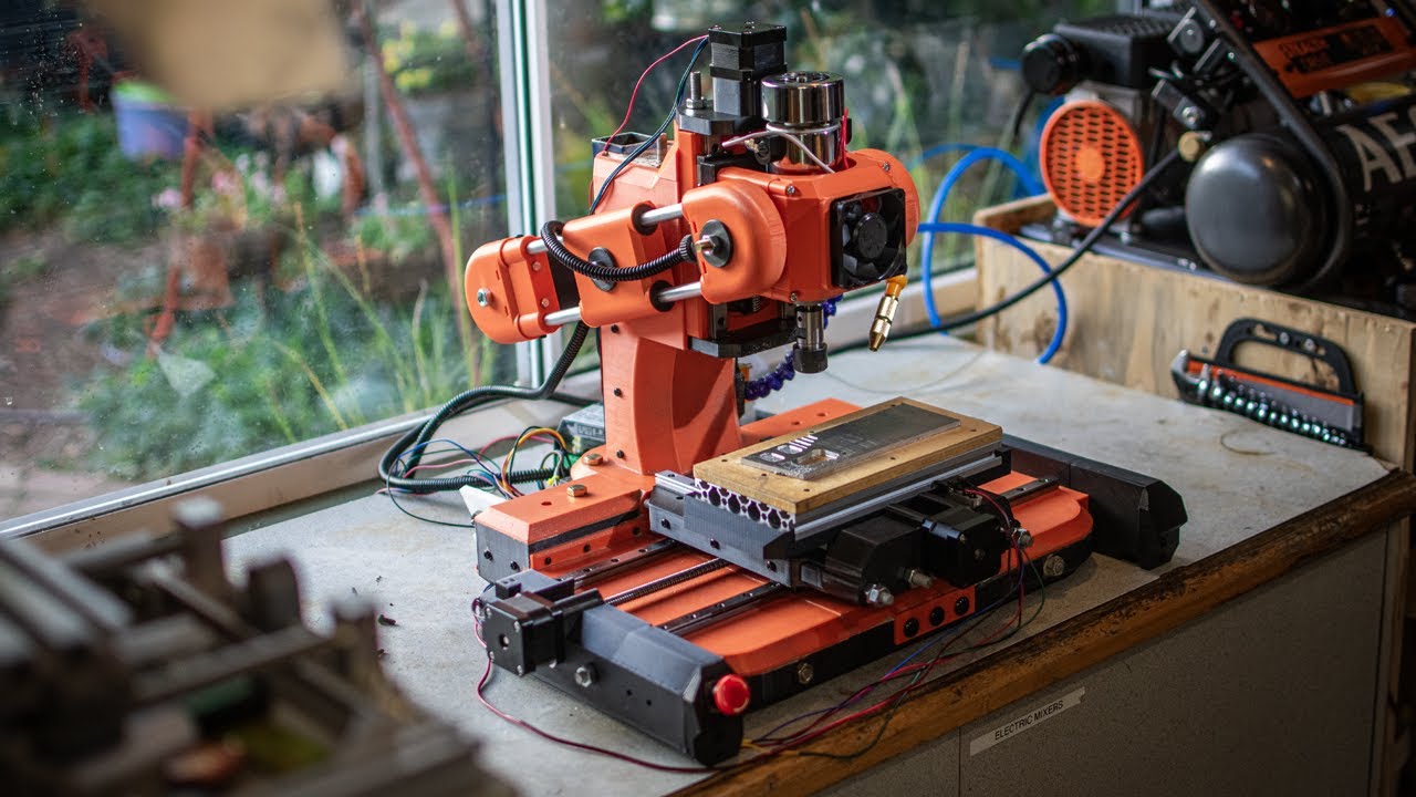
Manufacturing Insight: 3D Printed Desktop Cnc Mill
Introducing Precision Engineering Enabled by Honyo Prototype’s Industrial 3D Printing
The emergence of high-performance 3D printed desktop CNC mills represents a significant leap in accessible precision manufacturing for prototyping and low-volume production. These innovative machines demand components that withstand rigorous operational stresses while maintaining critical dimensional accuracy and thermal stability. At Honyo Prototype, we provide the essential industrial-grade 3D printing foundation that makes such advanced functional prototypes and end-use tools not only feasible but exceptionally reliable. Our specialized manufacturing capabilities directly address the demanding requirements of motion-critical applications like CNC systems.
Honyo Prototype leverages advanced industrial 3D printing technologies, including Metal Direct Metal Laser Sintering (DMLS) and high-temperature polymer processes using materials like ULTEM 9085 and PEEK. This enables the production of complex, integrated structural components, custom motor mounts, and precision lead screw assemblies with the necessary strength, stiffness, and thermal resistance required for stable milling operations. We achieve sub-100 micron dimensional accuracy and superior surface finishes on critical interfaces, ensuring the functional fidelity needed for consistent machine performance. Our rigorous process validation and material certification protocols guarantee that every printed part meets stringent industrial standards, moving far beyond basic prototyping to deliver production-intent solutions.
Partnering with Honyo Prototype accelerates the development and iteration of sophisticated electromechanical systems like desktop CNC mills by providing rapid access to high-integrity components. We understand the critical need for speed and reliability in bringing advanced manufacturing tools to market. To streamline your project initiation, utilize our Online Instant Quote system. Simply upload your CAD file to receive a comprehensive, detailed manufacturing assessment and competitive pricing within minutes, eliminating lengthy quotation delays and enabling immediate project progression. Experience how industrial 3D printing, executed to the highest engineering standards, transforms conceptual designs into robust, functional reality.
Technical Capabilities
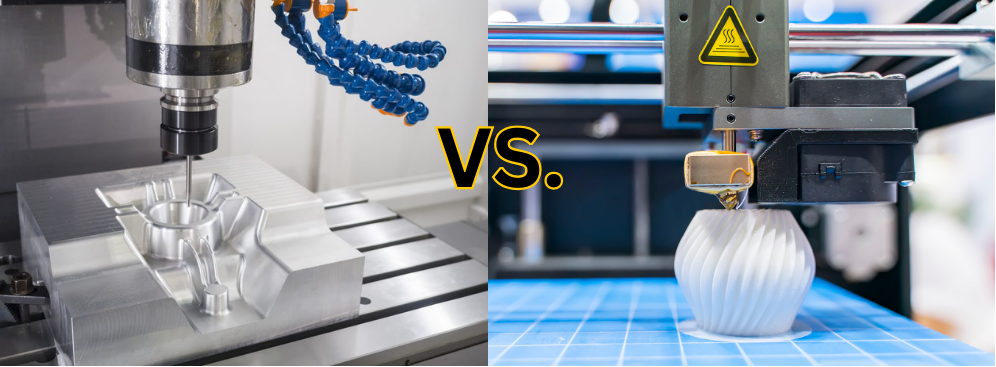
The term “3D printed desktop CNC mill” refers to a hybrid or conceptual system combining additive manufacturing (3D printing) and subtractive machining (CNC milling) capabilities, often at a desktop scale. In practice, while fully integrated desktop CNC mills with embedded 3D printing are rare, individual 3D printing technologies such as SLA, SLS, MJF, and DMLS are used to fabricate components or tooling for CNC applications. Below is a technical comparison of these 3D printing technologies in the context of producing functional parts relevant to desktop CNC mill systems, including material compatibility.
Technical Specifications of 3D Printing Technologies for Desktop CNC Mill Components
| Technology | Process Description | Build Volume (Typical Desktop/Compact) | Layer Thickness | Dimensional Accuracy | Surface Finish (Ra) | Compatible Materials (Relevant to CNC Mill Applications) | Post-Processing Requirements |
|---|---|---|---|---|---|---|---|
| SLA (Stereolithography) | Uses UV laser to cure liquid photopolymer resin layer by layer | 140 x 140 x 180 mm to 400 x 200 x 300 mm | 25–100 µm | ±0.1 mm | 0.8–1.6 µm | ABS-like resins, engineering resins (rigid, high-temp) | Support removal, IPA wash, UV curing |
| SLS (Selective Laser Sintering) | High-power laser sinters powdered polymer material | 150 x 150 x 150 mm to 300 x 300 x 300 mm | 80–120 µm | ±0.3 mm | 8–12 µm | Nylon (PA11, PA12), Glass-filled Nylon, TPU | Media blasting, heat treatment, infiltration (optional) |
| MJF (Multi Jet Fusion) | Inkjet array deposits fusing and detailing agents on nylon powder, heated by infrared | 380 x 280 x 380 mm | 80 µm | ±0.3 mm | 5–10 µm | Nylon (PA12), Glass-filled PA12, TPU | Media blasting, surface dyeing, heat treatment |
| DMLS (Direct Metal Laser Sintering) | High-power laser fully melts metal powder to form dense metal parts | 100 x 100 x 100 mm to 250 x 250 x 300 mm | 20–50 µm | ±0.1 mm | 10–20 µm (as-built), 2–5 µm (polished) | Aluminum (AlSi10Mg), Stainless Steel (17-4 PH, 316L), Tool Steel, Titanium | Stress relief, support removal, HIP, CNC finishing, polishing |
Material Notes:
ABS (Acrylonitrile Butadiene Styrene): Simulated via engineering-grade resins in SLA; not natively available in SLS or MJF. Offers good toughness and thermal stability for non-metal structural components.
Nylon (PA12, PA11): Native material for SLS and MJF. High strength-to-weight ratio, chemical resistance, and durability. Ideal for functional enclosures, gears, and mechanical parts in desktop CNC systems.
Aluminum (AlSi10Mg): Processed via DMLS. Used for lightweight, heat-dissipating components such as motor mounts or housings requiring thermal conductivity and rigidity.
Steel (Stainless Steel, Tool Steel): Processed via DMLS. Suitable for high-wear or load-bearing components like shafts, brackets, or custom tooling fixtures for milling applications.
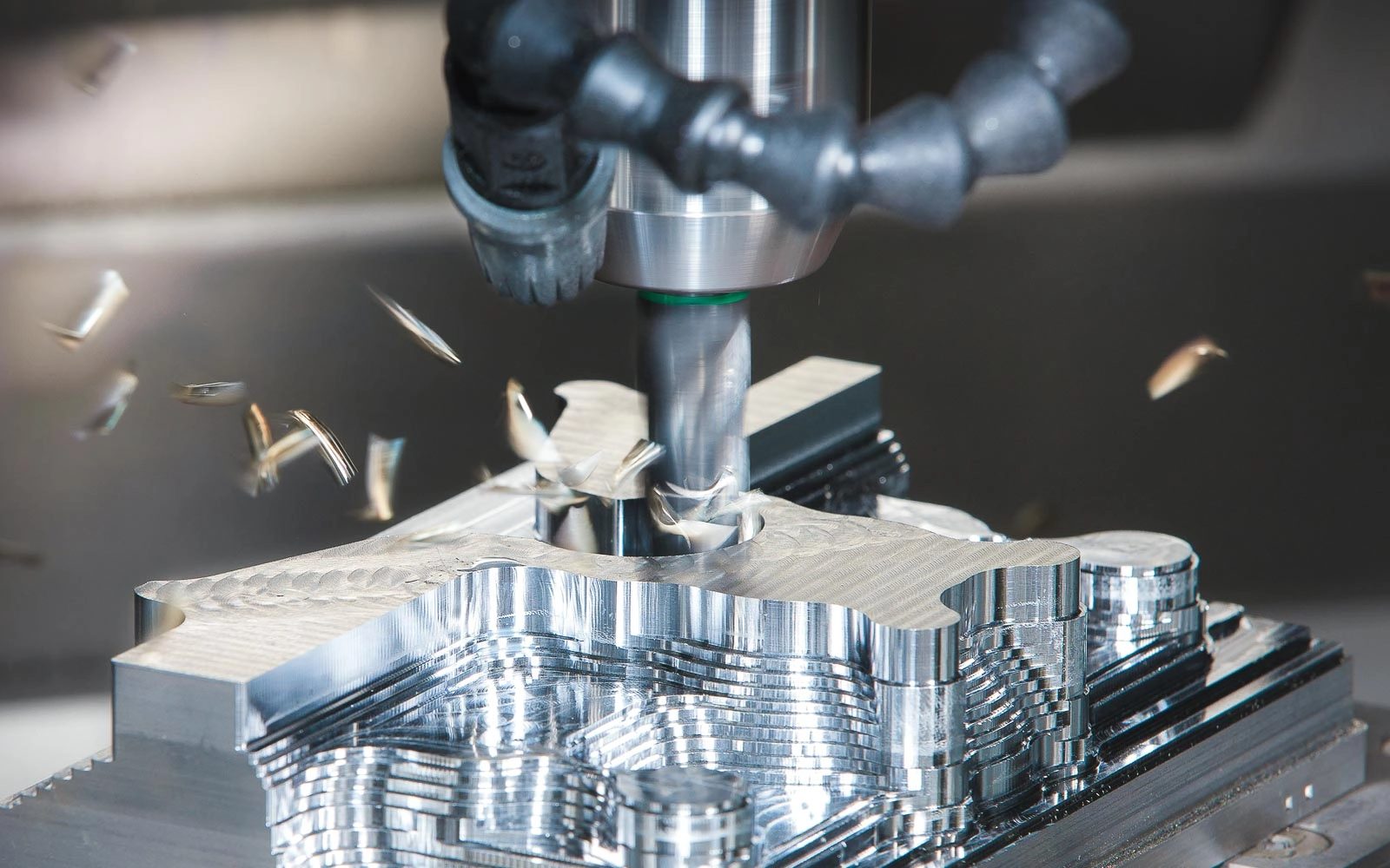
These technologies support the rapid prototyping and production of CNC mill subcomponents, custom tooling, or even end-use parts. While full metal desktop CNC mills are traditionally machined from billet, 3D printing enables complex geometries, topology-optimized structures, and faster iteration cycles in the design and manufacturing workflow.
From CAD to Part: The Process
Honyo Prototype delivers precision additively manufactured desktop CNC mill components through a rigorously controlled five-phase workflow designed for engineering-grade output. This process ensures dimensional accuracy, material integrity, and functional performance critical for motion-critical subsystems like spindle mounts, gantries, and tool changers.
CAD Upload and Validation
Clients submit native CAD files (STEP, Parasolid, or native SolidWorks) via our secure portal. Our system performs initial geometric validation, checking for watertight volumes, minimum feature sizes (≥0.4mm for metal printing), and overhang angles. For desktop CNC mill components requiring tight tolerances—such as linear guide rails or motor mounts—we verify alignment with ISO 2768-mK standards before proceeding. Unsupported geometries below 45° trigger automated notifications for client review.
AI-Powered Quoting Engine
Our proprietary AI analyzes the validated CAD against 12,000+ historical production datasets. For CNC mill parts, it prioritizes: material suitability (e.g., AlSi10Mg for lightweight gantries vs. Maraging Steel for high-stress spindle housings), build orientation impact on surface roughness (Ra ≤ 6.3µm as standard), and support structure complexity. The quote details cost drivers like internal channel accessibility for support removal—a critical factor for hollow tool changer assemblies. Typical turnaround is under 90 minutes with ±3% cost accuracy.
Engineering-Driven DFM Analysis
Certified manufacturing engineers conduct a tiered DFM review focused on CNC mill functional requirements. Key checks include:
| Parameter | Standard Check | CNC Mill Critical Focus |
|---|---|---|
| Wall Thickness | Min 0.8mm (metal) / 1.2mm (polymer) | Spindle housing thermal stability |
| Overhangs | Max 45° without supports | Gantry corner integrity under load |
| Hole Accuracy | ±0.1mm diameter tolerance | Linear bearing bore alignment |
| Surface Finish | As-printed Ra 12.5µm; post-processed to Ra 3.2µm | Motor mounting interfaces |
Thermal distortion simulations run for components exposed to >60°C during operation (e.g., near stepper motors). Non-compliant features receive specific redesign recommendations—such as converting deep pockets to lattice structures—to maintain stiffness while reducing mass.
Precision Production and Post-Processing
Approved designs move to our industrial metal (SLM/DMLS) or engineering polymer (SLS/MJF) systems. Desktop CNC mill components undergo:
Build plate calibration verified to ±10µm flatness
In-situ melt pool monitoring for defect prevention
Stress-relief annealing for metal parts (e.g., 315°C for 2 hours for AlSi10Mg)
Precision CNC milling of critical interfaces (e.g., ±0.025mm tolerance on linear rail mounting surfaces)
Vibration-assisted support removal for intricate internal channels
Coordinate measuring machine (CMM) validation against original CAD at 15+ critical points per assembly
Quality-Controlled Delivery
All shipments include:
First-article inspection report with GD&T callouts per ASME Y14.5
Material test certificates (e.g., ASTM F3318 for AlSi10Mg)
Stereolithography (STL) deviation map showing <±0.1% volumetric error
Functional test data for motion components (e.g., backlash measurements on printed lead screw nuts)
Standard lead time is 7–10 business days from CAD approval. Expedited 5-day service includes real-time production dashboards with layer-by-layer build logs. Every desktop CNC mill component ships in ESD-safe packaging with humidity indicators, accompanied by a traceability QR code linking to full production metadata. This end-to-end control ensures parts meet the dynamic loading and precision requirements inherent in CNC motion systems.
Start Your Project
Explore precision manufacturing with our 3D printed desktop CNC mill—ideal for prototyping and small-scale production. Engineered for accuracy and durability, this compact solution brings advanced machining to your workspace.
For sales inquiries, contact Susan Leo at [email protected]. Our manufacturing facility is based in Shenzhen, ensuring high-quality production and efficient delivery.
🚀 Rapid Prototyping Estimator
Estimate rough cost index based on volume.