Contents
Manufacturing Insight: 2.5 Axis Milling
Precision 2.5 Axis Milling: Strategic Efficiency for Complex Geometries
Honyo Prototype delivers optimized manufacturing solutions through advanced 2.5 axis CNC milling, a process engineered for components requiring precise pocketing, contouring, and drilled features across multiple planes without simultaneous multi-axis movement. This methodology provides a critical balance between cost-effectiveness and geometric capability, ideal for prismatic parts, molds, and tooling where full 3-axis complexity is unnecessary. Our shop-floor expertise ensures tight tolerances down to ±0.005 mm and superior surface finishes while minimizing non-productive machine time, directly reducing unit costs for low-to-mid volume production runs.
Unlike rudimentary 2D milling, 2.5 axis machining leverages Z-axis depth control to create tiered features with exceptional positional accuracy between layers—eliminating manual repositioning errors and accelerating throughput. Honyo’s certified technicians program and validate every operation using industry-leading CAM software, with rigorous in-process inspections guaranteeing first-article conformance. For engineering teams prioritizing speed-to-prototype without compromising dimensional integrity, our 2.5 axis service delivers repeatability that bridges the gap between basic machining and complex 5-axis workflows.
Accelerate your project timeline with Honyo’s Online Instant Quote system, providing detailed cost and lead-time estimates within minutes for 2.5 axis milling jobs. Upload CAD files to receive transparent pricing based on material, tolerances, and volume—enabling rapid design-for-manufacturability feedback before formal procurement. This digital workflow eliminates quotation bottlenecks, allowing engineering and procurement teams to iterate confidently while maintaining budget discipline.
| Process Capability | Key Benefit | Typical Applications |
|---|---|---|
| Z-axis depth control per operation | Eliminates manual repositioning errors | Enclosures, jigs, fixtures |
| Tolerances to ±0.005 mm | Consistent feature alignment across planes | Hydraulic manifolds, bracketry |
| Optimized toolpath sequencing | 25-40% faster cycle times vs. 3-axis for tiered geometries | Mold bases, casting patterns |
Technical Capabilities
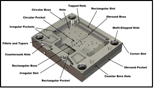
2.5 axis milling refers to a machining process where the cutting tool moves along two primary axes (X and Y) for positioning, while the third axis (Z) is used for depth control, typically in a plunging or drilling motion. Unlike full 3-axis milling, the tool orientation remains fixed in 2.5-axis operations, limiting simultaneous coordinated motion across all three axes. This method is ideal for prismatic parts, pocketing, drilling, and 2D profiling but is not suitable for complex sculpted surfaces.
Below is a comparison of key technical aspects across 2.5-axis, 3-axis, 4-axis, and 5-axis milling, as well as turning, with emphasis on tight tolerance capabilities and material compatibility.
| Feature | 2.5-Axis Milling | 3-Axis Milling | 4-Axis Milling | 5-Axis Milling | CNC Turning |
|---|---|---|---|---|---|
| Axis Movement | X, Y, Z (Z for depth only) | Full X, Y, Z coordinated motion | X, Y, Z + Rotary A-axis (X) | X, Y, Z + Two rotary (A/B or A/C) | X, Z + Rotary Chuck (C-axis optional) |
| Toolpath Capability | 2D profiling, drilling, pocketing | 3D contouring, complex faces | Indexing or continuous around X | Full simultaneous 5-axis contouring | Cylindrical, conical, threaded features |
| Typical Tolerance | ±0.005 mm to ±0.025 mm | ±0.005 mm to ±0.0125 mm | ±0.005 mm to ±0.0125 mm | ±0.005 mm to ±0.01 mm | ±0.005 mm to ±0.01 mm |
| Surface Finish (Ra) | 1.6 – 3.2 µm | 0.8 – 1.6 µm | 0.8 – 1.6 µm | 0.4 – 0.8 µm | 0.4 – 1.6 µm |
| Ideal for Complex Geometry | No | Limited | Moderate | Yes | No (except with live tooling) |
| Material Compatibility | Aluminum, Steel, ABS, Nylon | Aluminum, Steel, ABS, Nylon | Aluminum, Steel, ABS, Nylon | Aluminum, Steel, ABS, Nylon | Aluminum, Steel, ABS, Nylon |
| Aluminum Machinability | Excellent | Excellent | Excellent | Excellent | Excellent |
| Steel Machinability | Good (depends on alloy) | Good | Good | Good (with rigid setup) | Good |
| ABS Machinability | Good (low melting point) | Good | Good | Good | Fair (chip control critical) |
| Nylon Machinability | Fair (gummy, heat-sensitive) | Fair | Fair | Fair | Fair |
| Common Applications | Enclosures, brackets, jigs | Molds, housings, fixtures | Impellers, multi-face components | Aerospace parts, medical devices | Shafts, bushings, connectors |
Note: Tight tolerance performance depends on machine rigidity, tooling quality, thermal stability, and process control. 5-axis and advanced turning centers with Y-axis and live tooling can achieve the highest precision across complex part geometries. Materials like aluminum and steel are highly suitable for tight-tolerance work, while ABS and nylon require optimized feeds, speeds, and cooling strategies to maintain dimensional stability.
From CAD to Part: The Process
Honyo Prototype 2.5 Axis Milling Process Overview
Our streamlined workflow for 2.5 axis milling leverages automation and engineering expertise to deliver rapid, high-precision prototypes and low-volume production parts. The process is structured for efficiency while maintaining rigorous quality control at every stage.
Upload CAD
Customers initiate the process by uploading native or neutral CAD files (STEP, IGES, Parasolid, or native SOLIDWORKS formats) via our secure online portal. The system performs immediate validation checks for geometric integrity, unit consistency, and file completeness. Unsupported formats or corrupted files trigger an automated notification requesting resubmission, minimizing downstream delays. This step ensures the digital model aligns with manufacturing requirements before progressing.
AI Quote Generation
Upon successful CAD validation, our proprietary AI engine analyzes the geometry to generate an instant technical and commercial quotation within 15 minutes. The AI assesses feature complexity, material utilization, estimated machine time, and toolpath constraints specific to 2.5 axis operations. It cross-references real-time material costs, machine availability, and labor rates to provide a transparent cost breakdown. Critical manufacturability flags—such as undercuts incompatible with 2.5 axis motion or thin walls below minimum thresholds—are highlighted in the quote, enabling informed decisions prior to commitment.
DFM Analysis and Collaboration
Following quote acceptance, our manufacturing engineering team conducts a formal Design for Manufacturability review. This phase focuses exclusively on optimizing the design for 2.5 axis constraints: verifying all features are accessible via orthogonal X-Y-Z movements, confirming hole depths align with standard tool lengths, and ensuring wall thicknesses exceed machine rigidity limits. Engineers collaborate directly with the customer to resolve conflicts—for example, suggesting chamfers instead of sharp internal corners or adjusting draft angles for easier fixturing. A detailed DFM report with actionable recommendations is delivered within 24 hours, reducing iterations and accelerating production readiness.
Production Execution
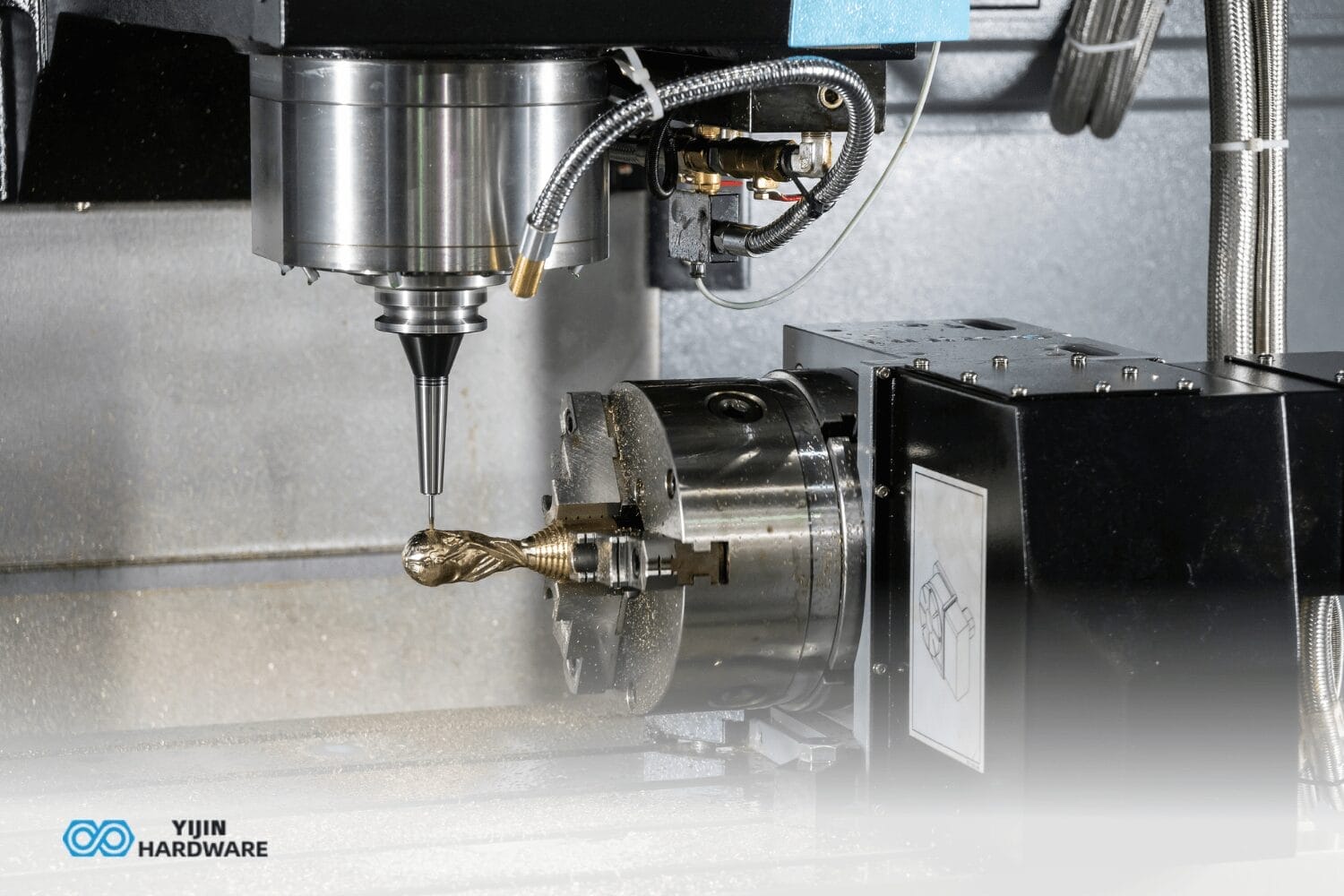
Approved designs move to production on Haas VF-2SS or DMG MORI 3-axis vertical machining centers operated in strict 2.5 axis mode. Key process parameters include:
Fixturing: Modular vise systems or custom soft jaws for repeatable workholding
Tooling: Standard end mills (2-4 flute) with adaptive roughing and constant Z-depth finishing
QC Integration: In-process CMM checks at critical stages (e.g., after roughing, before finish pass)
Material Handling: AS9100-certified traceability with lot-controlled stock
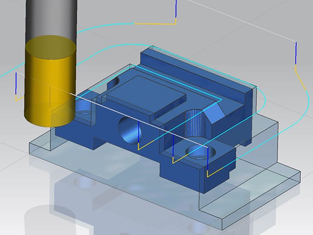
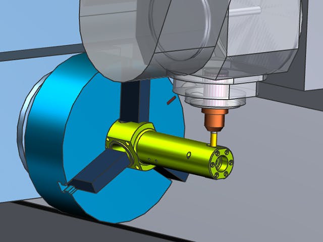
All toolpaths are generated using Mastercam with machine-specific post-processors to eliminate G-code errors. Production timelines are dynamically updated via our ERP system, with typical lead times of 3-7 business days for quantities under 50 units.
Delivery and Post-Production Support
Completed parts undergo final inspection per ASME Y14.5 GD&T standards, with first-article inspection reports provided upon request. Parts are packaged with anti-corrosion protection and shipped via DHL or FedEx with real-time tracking. A digital quality dossier—including dimensional reports and material certificates—is accessible through the customer portal. Our technical team remains available for post-delivery support, including engineering debriefs to refine future iterations.
2.5 Axis Capability Context
Understanding the distinction between process types is critical for optimal application. The table below clarifies where 2.5 axis milling delivers maximum value:
| Feature | 2.5 Axis Milling | Full 3-Axis Milling |
|---|---|---|
| Motion Capability | Simultaneous X-Y motion with Z indexing only | Continuous X-Y-Z interpolation |
| Ideal Applications | Prismatic parts, pockets, through-holes, 2D contours | Organic shapes, undercuts, turbine blades |
| Cost Efficiency | 30-40% faster setup vs. 3-axis; optimal for flat-bottomed features | Higher programming/setup costs for complex geometry |
| Honyo Utilization | 75% of prototype orders; fastest path for sheet metal brackets, jigs, and housings | Reserved for validated 3D contour requirements |
This structured approach ensures customers receive technically viable, cost-optimized solutions while leveraging Honyo’s specialization in rapid-turn, high-accuracy subtractive manufacturing.
Start Your Project
For precision 2.5-axis milling services, contact Susan Leo at [email protected]. Our advanced manufacturing facility in Shenzhen ensures high-quality, efficient production tailored to your prototyping and low-volume manufacturing needs. Let Honyo Prototype deliver accuracy and reliability for your next project.
🚀 Rapid Prototyping Estimator
Estimate rough cost index based on volume.